Gameduino + Mystorm = Oscilloscope!

There has to be more than one of us who over the years since the launch of systems like the original Game Boy have eyed up these handheld platforms and thought “You could make a really neat little oscilloscope with that!” But the commercial systems are closed-source, locked down, and proprietary, so in many cases there’s little easy prospect of such a device being created.

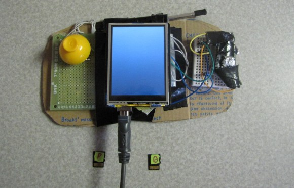
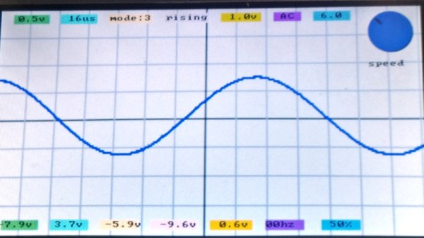
Fortunately though, there are now very accessible handheld gaming platforms, and [James Bowman], the creator of the Gameduino series of boards, writes in to tell us about an oscilloscope project for the Gameduino 3 created by [Lawrie Griffiths]. It uses a Mystorm FPGA board with an AN108 analogue board, and while the heavy lifting of acquisition is handled by the FPGA it is left to the Mystorm’s STM32 to talk to the Gameduino. There are a few teething troubles such as the Gameduino complaining when it is fed data too quickly, but the result is an effective 8 MHz bandwidth instrument with a touchscreen interface. He does however admit that the interface is a little fiddly at the moment. All the code is available via GitHub, so should you wish to pursue this particular avenue yourself, you can.

The Mystorm has made more than one appearance here over the years, and we’re sure we’ll see more. We saw it emulating a small OLED display to put Arduboy graphics on the big screen, for example, and implementing a complete Acorn BBC Micro home computer.

The BlueOkiris Gameduino Console

3011851406903369314

[Dylan] created an easy to make gaming console with an Arduino Uno, a makeshift button, an analog stick, and a TFT LCD touchscreen shield. Plus, he fashioned together a simple button with some duct tape.

So far, he has made 2 games. One is the infamous Pong. The other is a ‘Guess the Number’ type experience. The whole project is run within the code, and does not access the bootloader directly like you would with 2boots or a regular Gameduino adapter.

Build instructions can be found on [Dylan]’s hackaday.io project page (linked above). Essentially, all that is needed is to gather up the supplies, then take the button and analog stick and complete a circuit, fitting the open wires into the slots at digital pin 9. Solder the wires in place and connect ground to ground, 5v to 5v, x to A4, and y to A5. Add the TFT shield, insert a micro SD card, and upload a game.

To see it in action, check out the video after the break:

Continue reading “The BlueOkiris Gameduino Console”

MSP430 Gaming Shield Based On The Gameduino

Get your 8-bit gaming fix with this gaming shield for the TI Launchpad. It’s called the Launchpad GamingPack and was developed as part of TI’s 2012 Intern Design Contest. The team had just six weeks to complete the project.

The video after the break starts off with some fast-motion PCB layout. It is followed by footage of the board being populated, then anchored with graphics testing and some game play demonstrations. It looks like a real blast! NES controller ports were included on the board, and the device puts out 400×300 VGA, as well as audio.

As with the Gameduino, the hard work is done by the FPGA at the center of this board. It handles all of the VGA timing work, using what looks like 3-bit color. It is also responsible for generating the audio and monitoring the inputs. Since the team was under a time crunch the shield also includes a 10-pin header on the underside which was added for easy connection with a logic analyzer.

Continue reading “MSP430 Gaming Shield Based On The Gameduino”

Tracking Satellites With An Arduino

The guys over at brainwagon just finished up ANGST, the Arduino n’ Gameduinio Satellite Tracker, a build that displays 160 different satellites in Earth orbit on any SVGA monitor.

The build is of course based off an Arduino and Gameduino shield. A real-time clock is always needed for a satellite tracker, so a DS1307 RTC is thrown into the mix. The satellite data is stored on a 128KB EEPROM that is big enough to hold 750 different satellites and orbits.

The software side of things is a bit trickier. The guys at brainwagon used [James Miller]’s very popular and very old-school PLAN-13 sat tracking software. This orbit calculation program was published in 1983 and has since been ported from BBC Basic to just about every system imaginable.

Once the ANGST is hooked up and powered on, it reads the real-time clock and calculates the position of a satellite. This is done in real-time and updated every three minutes. On the screen, the last orbit (and a little more) is displayed along with the sun and the location of the ANGST. You might not find something like ANGST at the Space Command at NORAD, but we can’t think of a better way to keep track of the cubesats and spy sats above our heads.

Continue reading “Tracking Satellites With An Arduino”