What attracts a lot of people to amateur radio is that it gives you the ability to make your own gear. Scratch-building hams usually start by making their own antennas, but eventually, the itch to build one’s own radio must be scratched. And building this one-transistor transmitter is just about the simplest way to dive into the world of DIY radio.
Of course, limiting yourself to eight components in total entails making some sacrifices, and [Kostas (SV3ORA)]’s transmitter is clearly a study in compromise. For starters, it’s only a transmitter, so you’ll need to make other arrangements to have a meaningful conversation. You’ll also have to learn Morse code because the minimalist build only supports continuous-wave (CW) mode, although it can be modified for amplitude modulation (AM) voice work.
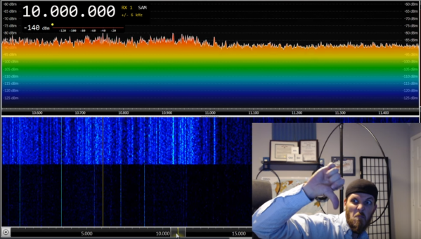
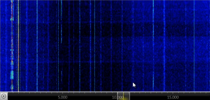
The circuit is flexible enough that almost any part can be substituted and the transmitter will still work. Most of the parts are junk-bin items, although the main transformer is something you’ll have to wind by hand. As described, the transformer not only provides feedback to the transistor oscillator, but also has a winding that powers an incandescent pilot lamp, and provides taps for attaching antennas of different impedances — no external tuner needed. [SV3ORA] provides detailed transformer-winding instructions and shows the final build, which looks very professional and tidy. The video below shows the rig in action with a separate receiver providing sidetone; there’s also the option of using one of the WebSDR receivers sprinkled around the globe to verify you’re getting out.
This little transmitter looks like a ton of fun to build, and we may just try it for our $50 Ham series if we can find all the parts. Honestly, the hardest to come by might be the variable capacitor, but there are ways around that too.
Continue reading “A One-Transistor Ham Transmitter Anyone Can Build”