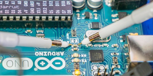
We won’t mention names, but we are always dismayed to see people twist knobs randomly on a scope until it shows a good picture. These days, there’s the dreaded auto button, too, which is nearly as bad. If you haven’t spent the time to learn how to properly use a scope [Bald Engineer] has a great introduction to making six measurements with an Arduino as a test device.
To follow along you’ll need an Arduino UNO and a two-channel (or better) scope. Actually, most of the measurements would probably work on any Arduino, but there are some that require the separate USB to serial chip like that found on the UNO and similar boards.
The six measurements are:
- The auto reset programming pulse
- Capture and decode serial data
- Noise on the power rail
- Observe probe loading effects
- PWM duty cycle
- The timing of pin manipulation code
Some of these measurements use a bit of Arduino code, while others just make use of the circuitry on the board no matter what software is running.
Not only does the post show you where to make the measurements and what the result should look like, there’s also a discussion of what the measurement means and some suggested things to try on your own.
If you go through this post, you might also enjoy learning more about probes. If you are feeling adventurous, you can even build your own current probe.


