Searchable KiCad Component Database Makes Finding Parts A Breeze

KiCad, the open source EDA software, is popular with Hackaday readers and the hardware community as a whole. But it is not immune from the most common bane of EDA tools. Managing your library of symbols and footprints, and finding new ones for components you’re using in your latest design is rarely a pleasant experience. Swooping in to help alleviate your pain, [twitchyliquid64] has created KiCad Database (KCDB). a beautifully simple web-app for searching component footprints.

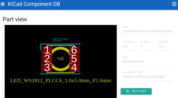
The database lets you easily search by footprint name with optional parameters like number of pins. Of course it can also search by tag for a bit of flexibility (searching Neopixel returned the footprint shown above). There’s also an indicator for Kicad-official parts which is a nice touch. One of our favourite features is the part viewer, which renders the footprint in your browser, making it easy to instantly see if the part is suitable. AngularJS and material design are at work here, and the main app is written in Go — very trendy.

The database is kindly publicly hosted by [twitchyliquid64] but can easily be run locally on your machine where you can add your own libraries. It takes only one command to add a GitHub repo as a component source, which then gets regularly “ingested”. It’s great how easy it is to add a neat library of footprints you found once, then forget about them, safe in the knowledge that they can easily be found in future in the same place as everything else.

If you can’t find the schematic symbols for the part you’re using, we recently covered a service which uses OCR and computer vision to automatically generate symbols from a datasheet; pretty cool stuff.

Learn Six Oscilloscope Measurements With One Arduino

We won’t mention names, but we are always dismayed to see people twist knobs randomly on a scope until it shows a good picture. These days, there’s the dreaded auto button, too, which is nearly as bad. If you haven’t spent the time to learn how to properly use a scope [Bald Engineer] has a great introduction to making six measurements with an Arduino as a test device.

To follow along you’ll need an Arduino UNO and a two-channel (or better) scope. Actually, most of the measurements would probably work on any Arduino, but there are some that require the separate USB to serial chip like that found on the UNO and similar boards.

The six measurements are:

  1. The auto reset programming pulse
  2. Capture and decode serial data
  3. Noise on the power rail
  4. Observe probe loading effects
  5. PWM duty cycle
  6. The timing of pin manipulation code

Some of these measurements use a bit of Arduino code, while others just make use of the circuitry on the board no matter what software is running.

Not only does the post show you where to make the measurements and what the result should look like, there’s also a discussion of what the measurement means and some suggested things to try on your own.

If you go through this post, you might also enjoy learning more about probes. If you are feeling adventurous, you can even build your own current probe.

Hackaday Links Column Banner

Hackaday Links: June 17, 2018

Do you like badges? Of course you like badges. It’s conference season, and that means it’s also badge season. Well good news, Tindie now has a ‘badge’ category. Right now, it’s loaded up with creepy Krustys, hypnotoads, and fat Pikas. There’s also an amazing @Spacehuhn chicken from [Dave]. Which reminds me: we need to talk about a thing, Spacehuhn.

On the list of ‘weird emails we get in the tip line’ comes Rat Grease. Rat Grease is the solution to rodents chewing up cabling and wires. From what we can gather, it’s a mineral oil-based gel loaded up with capsaicin; it’s not a poison, and not a glue. Rats are our friends, though, which makes me want to suggest this as a marinade, or at the very least a condiment. The flash point is sufficiently high that you might be able to use this in a fryer.

[Matthias Wandel] is the guy who can build anything with a table saw, including table saws. He posts his stuff online and does YouTube videos. A while back, he was approached by DeWalt to feature their tools in a few videos. He got a few hand tools, a battery-powered table saw, and made some videos. The Internet then went insane and [Matthias] lost money on the entire deal. Part of the reason for this is that his viewers stopped buying plans simply because he featured yellow power tools in his videos. This is dumpster elitism, and possibly the worst aspect of the DIY/engineering/maker community.

Elon Musk is the greatest inventor ever. No scratch that. The greatest person ever. Need more proof? The CEO of Tesla, SpaceX, and our hearts has been given the green light to build a high-speed underground train from Chicago O’Hare to downtown. Here’s the kicker: he’s going to do it for only $1 Billion, or $55 Million per mile, making it the least expensive subway project by an order of magnitude. Yes, Subways usually cost anywhere between $500 to $900 Million per mile. How is he doing it? Luck, skill, and concentrated power of will. Elon is the greatest human ever, and we’re not just saying that to align ourselves with an audience that is easy to manipulate; we’re also saying this because Elon has a foggy idea for a ‘media vetting wiki’.

There are rumors Qualcomm will acquire NXP for $44 Billion. This deal has been years in the making, with reports of an acquisition dating back to 2016. Of course, that time, the deal was set to go through but was apparently put on hold by Chinese regulators. Now it’s the same story again; there were recent rumors of Qualcomm buying NXP, and the story was later changed to rumors. We’re waiting for an actual press release on this one. It’s just another long chapter in the continuing story of, ‘where the hell are all the Motorola app notes and data sheets?’

Using IMUs For Odometry

The future is autonomous robots. Whether that means electric cars with rebranded adaptive cruise control, or delivery robots that are actually just remote control cars, the robots of the future will need to decide how to move, where to move, and be capable of tracking their own movement. This is the problem of odometry, or how far a robot has traveled. There are many ways to solve this problem, but GPS isn’t really accurate enough and putting encoders on wheels doesn’t account for slipping. What’s really needed for robotic odometry is multiple sensors, and for that we have [Pablo] and [Alfonso]’s entry to the Hackaday Prize, the IMcorder.

The IMcorder is a simple device loaded up with an MPU9250 IMU module that has an integrated accelerometer, gyro, and compass. This is attached to an Arduino Pro Mini and a Bluetooth module that allows the IMcorder to communicate with a robot’s main computer to provide information about a robot’s orientation and acceleration. All of this is put together on a fantastically tiny PCB with a lithium battery, allowing this project to be integrated into any robotics project without much, if any, modification.

One interesting aspect of the IMcorders is that they can be used for robot kidnapping issues. This, apparently, is an issue when it comes to robots and other electronic detritus littering the sidewalks. Those electric scooters abandoned on the sidewalk in several cities contain some amazing components that are ripe for some great hardware hacking. Eventually, we’re going to see some news stories about people stealing scooters and delivery robots for their own personal use. Yes, it’s a cyberpunk’s dream, but the IMcorder can be used for a tiny bit of theft prevention. Pity that.

Retrotechtacular: Car Navigation Like It’s 1971

Anyone old enough to have driven before the GPS era probably wonders, as we do, how anyone ever found anything. Navigation back then meant outdated paper maps, long detours because of missed turns, and the far too frequent stops at dingy gas stations for the humiliation of asking for directions. It took forever sometimes, and though we got where we were going, it always seemed like there had to be a better way.

Indeed there was, but instead of waiting for the future and a constellation of satellites to guide the way, some clever folks in the early 1970s had a go at dead reckoning systems for car navigation. The video below shows one, called Cassette Navigation, in action. It consisted of a controller mounted under the dash and a modified cassette player. Special tapes, with spoken turn-by-turn instructions recorded for a specific route, were used. Each step was separated from the next by a tone, the length of which encoded the distance the car would cover before the next step needed to be played. The controller was hooked to the speedometer cable, and when the distance traveled corresponded to the tone length, the next instruction was played. There’s a long list of problems with this method, not least of which is no choice in road tunes while using it, but given the limitations at the time, it was pretty ingenious.

Dead reckoning is better than nothing, but it’s a far cry from GPS navigation. If you’re still baffled by how that cloud of satellites points you to the nearest Waffle House at 3:00 AM, check out our GPS primer for the details.

Continue reading “Retrotechtacular: Car Navigation Like It’s 1971”

FPV-Rover 2.0 Has 3D Printed Treads And Plenty Of Zip

[Markus_p] has already finished one really successful 3D printed tracked robot build. Now he’s finished a second one using standard motors and incorporating what he learned from the first. The results are pretty impressive and you can see a video demo of the beast, below.

Most of the robot is PLA, although there are some parts that use PETG and flex plastic. There is an infrared-capable camera up front and another regular camera on the rear. All the electronics are pretty much off the shelf modules like an FPV transmitter and an electronic controller for the motors. There’s a servo to tilt the camera, as you can see in the second video.

The body fits together using nuts and magnets. The robot in the video takes a good beating and doesn’t seem to fall apart so it must be sufficient. What appealed to us was the size of the thing. It looks like it would be trivially easy to mount some processing power inside or on top of the rover and it could make a great motion base for a more sophisticated robot.

We’ve seen some similar projects, of course. This tracked robot uses mind control. And OpenWheel is a great place to get treads and other locomotion designs.

Continue reading “FPV-Rover 2.0 Has 3D Printed Treads And Plenty Of Zip”

Cheap Front Panels With Dibond Aluminium

The production capability available to the individual hacker today is really quite incredible. Even a low-end laser engraver can etch your PCBs, and it doesn’t take a top of the line 3D printer to knock out a nice looking enclosure. With the wide availability of these (relatively) cheap machines, the home builder can churn out a very impressive one-off device on a fairly meager budget. Even low volume production isn’t entirely out of the question. But there’s still one element to a professional looking device that remains frustratingly difficult: a good looking front panel.

Now if your laser is strong enough to engrave (and ideally cut) aluminum sheets, then you’ve largely solved this problem. But for those of us who are plodding along with a cheap imported diode laser, getting text and images onto a piece of metal can be rather tricky. On Hackaday.io, [oaox] has demonstrated a cost effective way to create metal front panels for your devices using a print service that offers Dibond aluminum. Consisting of two thin layers of aluminum with a solid polyethylene core, this composite material was designed specifically for signage. Through various online services, you can have whatever you wish printed on a sheet of pre-cut Dibond without spending a lot of money.

As explained by [oaox], the first step is putting together the image you’ll send off to the printer using a software package like Inkscape. The key is to properly define the size of the Dibond plate in your software and work within those confines, otherwise the layout might not look how you expected once the finish piece gets back to you. It’s also important to avoid lossy compression formats like JPEG when sending the file out for production, as it can turn text into a mushy mess.

When you get the sheet back, all you need to do is put your holes in it. Thanks to the plastic core, Dibond is fairly easy to cut and drill as long as you take your time. [oaox] used a step drill for the holes, and a small coping saw for the larger openings. The final result looks great, and required very little effort in the grand scheme of things.

But how much does it cost? Looking around online, we were quoted prices as low as $7 USD to do a full-color 4×4 inch Dibond panel, and one site offered a 12×12 panel for $20. For a small production run, you could fit several copies of the graphics onto one larger panel and cut them out with a bandsaw; that could drop the per-unit price to only a couple bucks.

We’ve seen some clever attempts at professional looking front panels, from inkjet printing on transparencies to taking the nuclear option and laser cutting thin plywood. This is one of those issues the community has been struggling with for years, but at least it looks like we’re finally getting some decent options.