Making Logic With Inductors

NOR

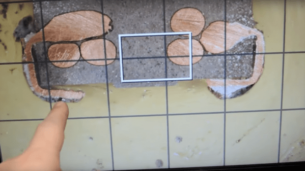
We’ve seen NAND and NOR logic gates – the building blocks of everything digital – made out of everything from marbles to Minecraft redstone. [kos] has outdone himself this time with a logic circuit we’ve never seen before. It’s based on magnets and induction, making a NOR gate out of nothing but a ferrite core, some wire, and a diode.

The theory of operations for this magnetic NOR gate goes as follows: If two of the input windings around the core have current passing in different directions, the fields cancel out. This could either be done by positive or negative voltages, or by simply changing the phase of the winding. To keep things simple, [kos] chose the latter. The truth table for a simple two-input, one-output gate gets pretty complicated (or exceedingly cool if you’d like to build a trinary computer), so to get absolute values of 1 and 0, a separate ‘clock’ winding was also added to the core.

One thing to note about [kos]’ gate is its innovation on techniques described in the relevant literature. Previously, these kinds of magnetic gates were built with square ferrites, while this version can work with any magnetic core.

While this isn’t a very practical approach towards building anything more complex than a memory cell, it is an exercise of what could have been in an alternate universe where tube technology and the transistor just didn’t happen.

Making A Power Inductor Checker

inductor-checker-for-oscilloscope

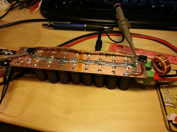
Back to the basics: there are three kinds of passive electronic components: Inductors, Capacitors and Resistors. An inductor can be easily built and many types of core and bobbin kits are available. However, characterizing one hypothetical coil you just made is quite tricky as its inductance will depend on the measurement frequency and DC bias current. That’s why [ChaN] designed the circuit shown above.

As you may guess, RF enthusiasts are more interested in the inductance vs frequency curve while power circuit designers prefer inductance vs load current (for a given frequency). The basic principle behind the circuit shown above is to load an inductor for repetitive short periods and visualizing the current curve with an oscilloscope connected to a sense resistor. When loading the inductor, the current curve will be composed of two consecutive slopes as at a given moment the coil’s core will be saturated. Measuring the slope coefficient then allows us to compute the corresponding inductance.

[Via Dangerous Prototypes]

Wireless Water Heater Monitor Uses Whatever Was Lying Around

[Chris] set out to build a monitoring system for his water heater. It doesn’t Tweet or send SMS messages. It simply lights up an LED when the water heater is active. The one thing that complicates the setup is that he didn’t want to pull any wire from the garage into the house. What you see above is the wireless setup he used to accomplish this goal.

This is an electric water heater, so [Chris] patched into the 230V heating element feed. When the water heater is idle this connection is cut off. He used a transformer to step the voltage down to 17V and rectified it before feeding a 7805 power regulator. The rest of the transmitter circuit consists of a 555 timer driving the coil seen on the left. It is made out of telephone wire, with each of the four conductors inside connected together to multiply the number of windings. The box of breakfast sausages hosts the receiver coil. His hardware takes the induced current from that coil and amplifies it, feeding the signal to the base of a transistor responsible for switching the status LED. This works through the 6″ thick garage wall, although he did have to use a battery on the receiving end as his wall wart was injecting way too much noise into the system to work.

EMF Oscilloscope Probe

[Tuomas Nylund] wanted a way to visualize the electromagnetic fields (EMF) around him. He figured the oscilloscope was the tool best suited for the task, but he needed a way to pick up the fields and feed them into one of the scope’s probes. He ended up building this EFM probe dongle to accomplish the task.

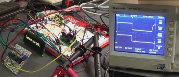
He admits that this isn’t much more than just an inductor connected to the probe and should not be used for serious measurements. But we think he’s selling himself short. It may not be what he considers precision, but the amplification circuit and filtering components he rolled into the device appear to provide very reliable input signals. We also appreciate the use of a BNC connector for easy interface. Check out the demo video after the break to see the EMF coming off of a soldering station controller, from a scanning LCD screen, and that of a switch-mode power supply.

Continue reading “EMF Oscilloscope Probe”

Metal Detection Using An Inductor Instead Of A Clock Crystal.

This project from a few years back is an interesting take on a metal detector. Instead of building a detection circuit, [Bruno Gavand] replaced the external clock crystal with an inductor. Here you can see the inductor coil next to the PIC 12F683. You can see two components jumping from one breadboard to the other. These are smoothing capacitors on the inductor lines.

The watchdog timer for the chip is run by the internal RC oscillator. When the external crystal receives a pulse due to metal inducing a current in the coil, the value of the watchdog timer is compared to it. This data is filtered and if the proper parameters are present the green LED blinks. This is bicolor LED. If the inductor circuit is functioning properly it will blink red at power up. [Bruno] says that results will vary based on that inductor so you may need to try a few to get the calibration light to blink.

We’re thinking this would make a simple stud finder (by detecting where the nails/screws are in the wall). Check out the demo after the break, then let us know what you would use this for by leaving a comment.

Continue reading “Metal Detection Using An Inductor Instead Of A Clock Crystal.”

Barebones PIC RFID Tag

An inductor and 8-pin microcontroller are all that make up this barebones RFID tag. You might have done a double-take when first seeing the image above. After all, there’s nothing hooked up to the power and ground pins on the chip. As [Ramiro Pareja] explains in his post, the power is actually supplied via the I/O pins to which the inductor is soldered. It seems that each I/O pin has a parasite capacitor and a pair of clamping diodes inside the chip. When the AC current that is induced by the magnetic field of the RFID reader hits those pins, the capacitors charge and the clamping diodes form a bridge rectifier. This results in power being injected into the chip, which turns around and sends the RFID code back through the inductor.

This isn’t the first time that we’ve seen this concept. We featured a hack that is exactly the same except it used an AVR chip. This one uses a PIC 12F683 but should work with just about any 12F or 16F model. The code is written in Assembly and shouldn’t need any changes for different hardware. [Ramiro] does talk a bit about adding a decoupling capacitor to Vss and Vdd, as well as a tuning capacitor to the two I/O pins used above to help make the device a little more robust. But, as you can see in the video after the break, it works just fine without them.

Continue reading “Barebones PIC RFID Tag”

Beginner Concepts: A Quartet Of Videos On Inductors

Inductors can be found in many of the devices you use every day, but if you’ve been working only with DC in your projects there’s a good chance you’ve never needed to know anything about them. Now’s your chance to pick up on the basics with this video tutorial series. [Afroman] put together four short videos that we’ve embedded after the break. Set aside fifteen minutes to watch them; you’ll be glad you did.

The first in the series starts out by explaining that an inductor is a coil of wire that serves a similar function as a capacitor with one major difference. A capacitor stores voltage, while an inductor stores current. In the second video, [Afroman] hooks up some inductors to a square-wave generator, then measures the resulting current characteristics using an oscilloscope. He shows the difference between inductor core material (air core versus ferrite core) and illustrates the properties that make inductors so useful as filters. The third video covers filtering circuits, and the fourth is the best explanation of why you need a flyback diode when driving a motor (an inductive load) that we’ve seen yet.

Continue reading “Beginner Concepts: A Quartet Of Videos On Inductors”