2025 Component Abuse Challenge: An Input Is Now An Output

Part of setting up a microcontroller when writing a piece of firmware usually involves configuring its connections to the outside world. You define a mapping of physical pins to intenral peripherals to decide which is an input, output, analogue, or whatever other are available. In some cases though that choice isn’t available, and when you’ve used all the available output pins you’re done. But wait – can you use an input as an output? With [SCART VADER]’s lateral thinking, you can.

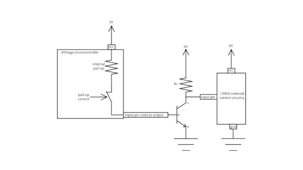
The whole thing takes advantage of the internal pull-up resistor that a microcontroller has among its internal kit of parts. Driving a transistor from an output pin usually requires a base resistor, so would it be possible to use the pullup as a base resistor? If the microcontroller can enable or disable the resistor on an input pin then yes it can, a transistor can be turned off and on with nary an output to be seen. In this case the chip is from ATmega parts bin so we’re not sure if the trick is possible on other manufacturers’ devices.

As part of our 2025 Component Abuse Challenge, this one embodies the finest principles of using a part in a way it was never intended to be used, and we love it. You’ve still got a few days to make an entry yourself at the time of writing this, so bring out your own hacks!

What’s The Cheapest Way To Scan Lots Of Buttons?

So you’re building a new mechanical keyboard. Or attaching a few buttons to a Raspberry Pi. Or making the biggest MIDI grid controller the world has ever know. Great! The first and most important engineering question is; how do you read all those buttons? A few buttons on a ‘Pi can probably be directly connected, one for one, to GPIO pins. A mechanical keyboard is going to require a few more pins and probably some sort of matrix scanner. But the grid controller is less clear. Maybe external I/O expanders or a even bigger matrix? Does it still need diodes at each button? To help answer these questions the folks at [openmusiclabs] generated a frankly astounding map which shows, given the number of inputs to scan and pins available, which topology makes sense and roughly how much might it cost. And to top it off they link into very readable descriptions of how each might be accomplished. The data may have been gathered in 2011 but none of the fundamentals here have changed.

How do you read this chart? The X axis is the number of free pins on your controller and the Y is the number of I/Os to scan. So looking at the yellow band across the top, if you need to scan one input it always makes the most sense to directly use a single pin (pretty intuitive, right?). Scrolling down, if you need to read 110 inputs but the micro only has eight pins free there are a couple choices, keys E and F. Checking the legend at the top E is “Parallel out shift register muxed with uC” and F is “Parallel in shift register muxed with uC“. What do those mean? Checking the table in the original post or following the link takes us to a handy descriptive page. It looks like a “parallel out shift register” refers to using a shift register to drive one side of the scan matrix, and “parallel in shift register” refers to the opposite.

Continue reading “What’s The Cheapest Way To Scan Lots Of Buttons?”

ATtiny Chip Abused In RFID Application

One of Atmel’s smallest microcontrollers, the ATtiny, is among the most inexpensive and reliable chips around for small applications. It’s also one of the most popular. If you don’t need more than a few inputs or outputs, there’s nothing better. As a show of its ability to thrive under adverse conditions, [Trammell Hudson] was able to shoehorn an ATtiny into an RFID circuit in a way that tests the limits of the chip design.

The RFID circuit only uses two of the ATtiny’s pins and neither of which is the ground or power pin. The ATtiny is equipped with protective diodes on its input pins, and if you apply an AC waveform to the input pins, the chip is able to use the leakage current to power itself. Once that little hurdle is crossed, the ATtiny can do the rest of its job handling the RFID circuitry.

This project takes a deep dive into the internals of the ATtiny. If you’ve ever wondered what was going on inside of everyone’s favorite tiny microcontroller, or if you’re looking for an RFID circuit that keeps parts counts to an absolute minimum, this is the project for you.  The ATtiny is more than just a rugged, well-designed chip, though. It’s capable of a lot more than such a small chip should be able to.

Thanks to [adnidor] for the tip!