Porting the original DOOM to various pieces of esoteric hardware is a rite of passage in some software circles. But in the modern world, we can get better performance than the 386 processor required to run the 1993 shooter for the cost of a dinner at a nice restaurant — with plenty of other embedded systems blowing these original minimum system requirements out of the water.
For a much tougher challenge, a group from Silicon Labs decided to port DOOM‘s successor, Quake, to the Arduino Nano Matter Board platform instead even though this platform has some pretty significant limitations for a game as advanced as Quake.
To begin work on the memory problem, the group began with a port of Quake originally designed for Windows, allowing them to use a modern Windows machine to whittle down the memory usage before moving over to hardware. They do have a flash memory module available as well, but there’s a speed penalty with this type of memory. To improve speed they did what any true gamer would do with their system: overclock the processor. This got them to around 10 frames per second, which is playable, but not particularly enjoyable. The further optimizations to improve the FPS required a much deeper dive which included generating lookup tables instead of relying on computation, optimizing some of the original C programming, coding some functions in assembly, and only refreshing certain sections of the screen when needed.
On a technical level, Quake was a dramatic improvement over DOOM, allowing for things like real-time 3D rendering, polygonal models instead of sprites, and much more intricate level design. As a result, ports of this game tend to rely on much more powerful processors than DOOM ports and this team shows real mastery of their hardware to pull off a build with a system with these limitations. Other Quake ports we’ve seen like this one running on an iPod Classic require a similar level of knowledge of the code and the ability to use assembly language to make optimizations.
Thanks to [Nicola] for the tip!


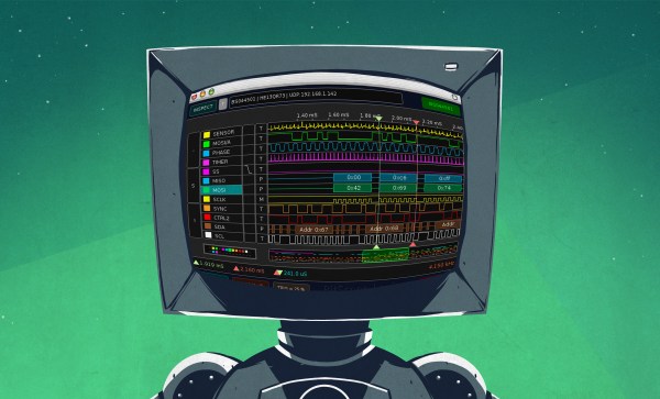
 In this article, let’s figure out places where you can use a logic analyzer, and places where you can’t. We’ll start with the first limitation of logic analyzers – capture speed. For instance, here’s a cool thing you can buy on Aliexpress – a wristband from TTGO that looks like a usual fitness tracker, but has an ESP32 in it, together with an IMU, an RTC, and an IPS screen! The seller also has an FFC-connectable devboard for programming this wristband over UART, plus vibromotor and heartrate sensor expansion modules.


