A Beginner’s Guide To LED Matrices

led_tutorial

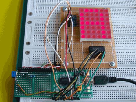
[Rajendra Bhatt] wrote in to share a tutorial he put together demonstrating the basics of using LED dot matrix displays. While this subject might be old hat to many out there, his helpful walkthroughs are geared more towards beginners who are exploring various electronics concepts for the first time.

He explains the theory behind LED displays using a PIC-driven 5×7 matrix as an example. He discusses persistence of vision and how tricking the human eye can save you quite a bit of time and a whole lot of pins. Multiplexing is broken down into its most basic steps, which [Rajendra] illustrates by showing how a letter would be drawn on the LED display one column at a time. The use of a ULN2803A Darlington Array is also discussed, and he details why it is used when pulling the five columns of LEDs to ground.

The only portion of the tutorial we thought could be expanded upon was the programming section. While he does show how each letter of the alphabet can be displayed via a series of five hex values, he does not cover the “why” part of the process. Obviously while anyone familiar with binary and hex can figure it out in pretty short order, we think that it would be a great place to pause and expand the readers’ knowledge even more.

Overall it’s a useful tutorial, and most beginners would likely find it quite helpful.

Webcam Images Processed And Played Back On LED Display

[Mathieu] has bee working to refine the code running on an LED matrix, and added some neat display tricks along the way. He wanted to make the display directly addressable from a computer. The 96×64 bi-color LED display is powered by an Atmel FPSLIC and already used double-buffering. Enabling a PC to write directly to one of the buffers was not too hard, requiring just a bit of optimization to get the timing right. From the look of the video after the break, he nailed it.

The video feed is generated from a webcam stream using Matlab to process each image. Just 50 lines of code captures a frame, sizes it appropriately, converts the result to black and white for edge detection, then finishes the job by compressing image data for transmission to the embedded processor. We’d like to say it’s easier that it sounds but we’re pretty impressed with this work. The display manages about 42 Hz with the current setup.

Continue reading “Webcam Images Processed And Played Back On LED Display”

A Charlieplex Display And A Board Layout Tip

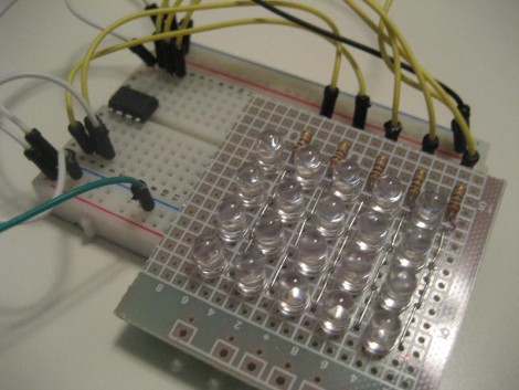
[Ben] is getting himself up to speed with microcontrollers. He jumped into the deep end by taking on this Charlieplex LED matrix build. As you can see after the break, he not only made the display work, but coded Conway’s game of life to run on the ATtiny85 that drives the device. What you see above is the prototype version that [Ben] used to make sure he had the hardware just right. He’s seeing the project through to a manufactured board and this is where the layout tip comes from. In order to make sure he had enough space for all of his components he printed out the board artwork, taped it to some Styrofoam, and then inserted all of the through-hole parts. Now he can be sure that physically the design works, we’ll keep our fingers crossed that everything is also kosher electrically.

Continue reading “A Charlieplex Display And A Board Layout Tip”

See-through LED Display

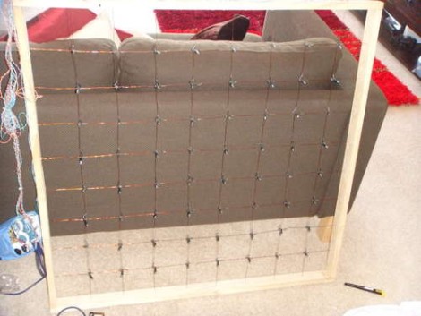
[Ndsit] is having a party and wanted to liven up the place with some blinky lights. He’s a bit new when it comes to hobby electronics, and although we’d highly recommend inviting some resistors to participate, the LED matrix that he built is very nice. It’s 8×8, it’s big, and (as shown in the clip after the break) the lights seem to hover in midair. That’s because he didn’t use a substrate to make the display. A grid of enameled wire is strung between the four sides of the wooden frame. LEDs were gathered from a string of Christmas lights which means they’re in a holder and have insulated wires already connected. Each one was tied on at a junction point of the grid, then connected to a portion of the wire where enamel had been scraped off.

It works but there’s already one light that is out. We hope some current protection is added so that this can be used again and again.

Continue reading “See-through LED Display”

Bi-color LED Matrix Clock Uses Point-to-point Construction

[Daniel] wanted his child to stay in bed until a semi-decent time each morning. The problem is the kid doesn’t know how to read a clock, so [Daniel] built him a clock. Yeah, doesn’t make much sense to us either, but we’ve used our own shaky premises for projects so who are we do judge?

He used a bi-color 8×8 LED matrix as the clock display. What caught our eye is the point-to-point soldering he used for the three strip boards that make up the device. Note the use of a drill-bit to break the traces when needed. Each board has its own purpose; the matrix drive, the logic board, and the power board. A PIC 18F4550 lets [Daniel] control the clock via USB, and takes care of lighting up the hour as a red number when it’s time to sleep, and a green one when it’s okay to arise. There’s a flashing pixel for seconds, and a binary readout of minutes along the bottom.

We’ve asked [Daniel] to post a schematic and an image of the clock face when displaying the time. No word yet but we’ll keep our eye on it. In the mean-time, check out this clock that uses an RGB 8×8 LED matrix.

Barcode Challenge For Radio Operators

[Scott Harden] came across a few posts about QR code matrix barcodes coming through on the 40m baud radio band. A few operators had captured the signals and assembled them into the code block seen above but they weren’t able to get a clear enough shot for a smartphone to decode the image. [Scott] took on the challenge and decoded the mysterious message himself. He tried some graphic editing to separate and enhance the color channels in order to up the contrasts of the image. This helped, but still couldn’t be read automatically. In a move similar to those seen in Hackaday’s own barcode challenges he dropped the image into Inkscape so that he could manually clean it up. Once it was overlaid on a grid the job was pretty simple. the left side did require some more image manipulation and precision”squinting” to eliminate interference from the vertical banding, but he managed to get the message. We won’t spoil it here in case you want to take on the challenge yourself. Good luck!

Communicating With An LED Matrix

Most of the LED matrix posts we run delve into the hardware design. This time around [J Bremnant] used prefab modules and focused on writing code to address the display. The hardware combines two 24×16 LED boards from Sure Electronics with a Teensy 2.0 to drive the display and provide a USB connection. The firmware comes in just under 8k, leaving graphic manipulation up to a PC.

[J Bremnant’s] Python script offers a lot of flexibility when working with the display. There are three modes selectable through a terminal interface. One just tests the display and then drops into Conway’s Game of Life. The second mode lets you send commands via serial interface so it can be used as a message ticker. The final feature is frame addressing that allows graphics to be dropped into the display. See each of these featured in the video after the break.

Continue reading “Communicating With An LED Matrix”