3D Render Live With Kinect And Bubble Boy

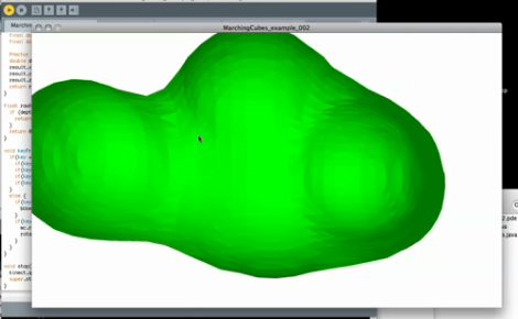
[Mike Newell] dropped us a line about his latest project, Bubble boy! Which uses the Kinect point cloud functionality to render polygonal meshes in real time.  In the video [Mike] goes through the entire process from installing the libraries to grabbing code off of his site. Currently the rendering looks like a clump of dough (nightmarishly clawing at us with its nubby arms).

[Mike] is looking for suggestions on more efficient mesh and point cloud code, as he is unable to run any higher resolution than what is in the video. You can hear his computer fan spool up after just a few moments rendering! Anyone good with point clouds?

Also, check out his video after the jump.

Continue reading “3D Render Live With Kinect And Bubble Boy”

Marble Machines Roundup

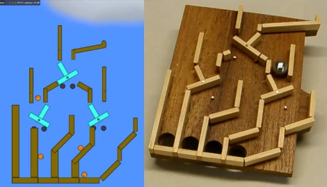
[Denha’s] been building marble machines for years and decided to look a back on some of his favorite marble-based builds  (translated). There’s a slew of them, as well as some thoughts about each. Our favorite part is the digital simulations of the projects. For instance, the image above shows a flip-flop marble machine that was built in a physics simulator. This makes it a lot easier to plan for the physical build as it will tell you exact dimensions before you cut your first piece of material. Both of these images were pulled from videos which can be seen after the break. But this isn’t the most hard-core of pre-build planning. SolidWorks, a CAD suite that is most often used to design 3D models for precision machining, has also been used to model the more intricate machines.

Continue reading “Marble Machines Roundup”

Building Your Own Router Lift-out Mechanism

Adjusting the bit height on a router table can be a pain in the butt. Traditionally you needed to get into the cavity under the table top in order to make these adjustments, and it’s hard to make the adjustment and measure the height at the same time. Modern routers now offer the option to adjust height through a hole in the plate that sits in the router table, but this is usually only found on the more expensive models. Rather than buy a new tool [Urant] built his own router lift.

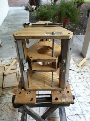
He’s using recycled closet rails to give his rig some smooth operation. These are the rails and runners that let closet doors hang from the top jamb. He saved them when replacing the closet doors in one of his rooms. There’s a triangular gantry which hosts the router, allowing it to move vertically on the three sets of rails. The threaded rod in the foreground of the picture above lets the woodworker adjust bit height by turning the nut at the top. Once mounted in the router table the nut is accessible through a small hole in the table surface.

LED Matrix Glasses Keep All Eyes On You

my_shades_are_so_bright_i_gotta_wear_um_something

Instructables user [llopez-garcia] was looking for something that would make him stand out at music events or clubs, and decided that an LED matrix built into a set of sunglasses would do the trick.

He grabbed some LEDs and the biggest pair of sunglasses he could find at WalMart, then he got down to business. He had no experience in programming micro controllers, so he chose a PICAXE 20X2 to run his glasses, figuring that it would be easier to program in BASIC for his first project than C.

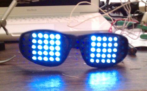
He drilled holes in the lenses and wired up two 5×5 LED grids, connecting them to the PICAXE as a single 10×5 array. That setup was chosen because the 20X2 limited him to 15 usable pins and he wanted to avoid using a shift register or LED driver to keep the part count down. The rest of the build is relatively straightforward with resistors in all the right places, and a pair of AAA batteries to power it – one strapped to either temple.

We think these are pretty cool, though we’re not sure if he can see anything while wearing them. Then again, who cares? You don’t need to be able to see with glasses this awesome.

If he had to do it all over again, [llopez-garcia] says he would beef up the LED structure a bit, as well as choose a different micro controller that can be programmed in C since he felt the PICAXE was a bit limited by BASIC.

Stick around to see a quick demo video of the glasses in action.

Continue reading “LED Matrix Glasses Keep All Eyes On You”

Large Remote-controlled Game Of Life Display

game_of_life

Sometimes it’s just plain fun to over-engineer. [Stephanie] gets a warm fuzzy feeling when she successfully adds way more electronics components to a project than she really needs – just because she can. We can’t really argue with her if that is the intended goal, nor can we find fault with the sweet Game of Life display she put together.

She started off with six Game of Life kits from Adafruit, but she quickly caught the LED bug and her collection grew until she had 20 kits (that’s 320 LEDs for those of you keeping count). After piecing them all together, they were mounted in a wooden frame and placed behind a dark piece of acrylic. It looked great and worked just fine, but it wasn’t overdone enough for her tastes.

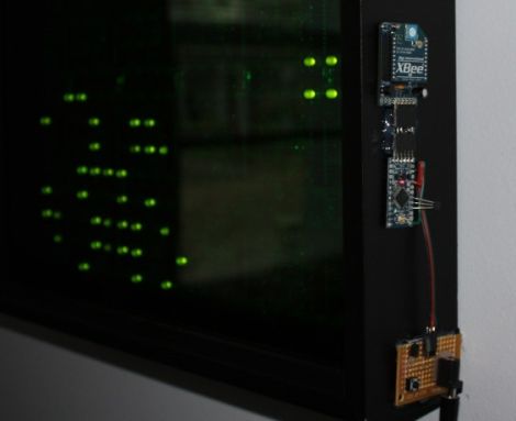
In the end, she added a small Arduino and Xbee module to the Game of Life display, which enables it to be controlled by her network-enabled thermostat we featured a few weeks back. The thermostat was fitted with an Xbee unit as well, which allows it to turn the Game of Life on and off at whatever times [Stephanie] specifies.

We’ll take two please.

[via Adafruit Blog]

Egg Clock (it’s Egg-ceptional)

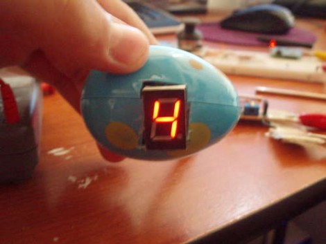
Easter is over and with some plastic eggs still on hand, [Franspaco] was looking for something to do with them. He decided to use an egg as an enclosure for a digital clock.

You can see that the finished project uses just one 7 segment LED display to show the time. A scrolling number method is used to delineate each digit of the 24-hour time readout. The display will go blank, followed by two numbers for the hours, a dash as a separator, and finally two more digits for the minutes. A PICAXE microcontroller drives the clock, but for accuracy a DS1307 does the timekeeping.

[Franspaco] etched his own circuit board that is sized to fit perfectly, housing the two chips, an LED, and a programming header. The on-board LED blinks at 1 Hz, giving some inner glow to the plastic shell. He accomplished most of his goals, but was unable to fit the batteries inside of one egg, prompting the need for a tethered power-egg. If he moves to surface mount components for the next generation of this device we think he’ll have no problem fitting a small battery (like an A23) inside.

Old Computer Parts Demonstrate How Particle Accelerators Work

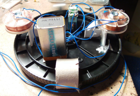
[Ameres Valentin] writes in to let us know about his DIY particle accelerator model. The model, made mostly out of old computer stuff, mimics a linear high-energy particle accelerator which use drift tubes to toss particles around. Drift tubes work by first attracting a particle (in this case, ball bearing) until it crosses a charged plate (in this case, coil), then flipping the charge polarity and repelling the particle.  In this case the accelerators function more like a multiple coil gun, as they can’t exactly push the bearing away. Regardless of the specifics the model is an excellent visual aid.

As the bearing rolls along the rails of the CD spindle it shorts bits of foil tape placed just ahead of the magnets. This (appears) to flip a relay that switches on the magnet. Once the magnet coil is energized it pulls the bearing towards its center, accelerating it. The foil stops just before the point where the magnet would pull back the bearing. We are not sure if [Ameres] is using any trickery to get the magnets to individually power, as schematics are not available. The circuit should be simple enough to figure out with a couple relays. In the video [Ameres] adds a lamp to the coils to display when they are powered. Nice work! This could make a fun distraction desk accessory, better than those clicky Newton’s cradles.

Check out [Ameres]’ site for a video of the model in action.