Garbage Can CNC Machine Build

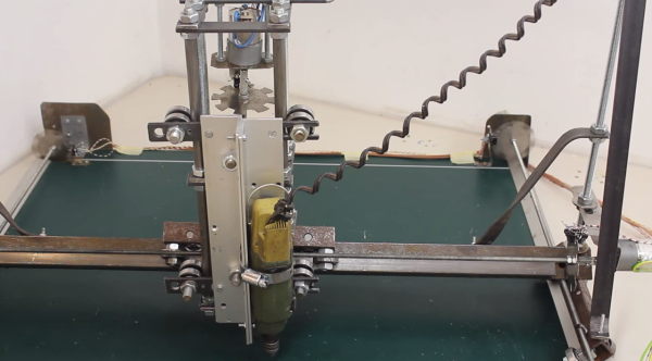
Forget sourcing parts for your next project from some fancy neighborhood hardware store. If you really want to show your hacker chops, be like [HomoFaciens] and try a Dumpster dive for parts for a CNC machine build.

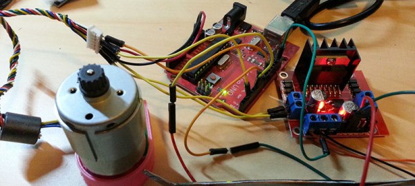
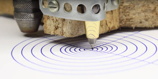
OK, we exaggerate a little – but only a little. Apart from the control electronics, almost everything in [HomoFacien]’s build could be found by the curb on bulk-waste pickup day. Particle board from a cast-off piece of flat-pack furniture, motors and gears from an old printer, and bits of steel strapping are all that’s needed for the frame of a serviceable CNC machine. This machine is even junkier than [HomoFacien]’s earlier build, which had a lot more store-bought parts. But the videos below show pretty impressive performance nonetheless.

Sure, this is a giant leap backwards for the state of the art in DIY CNC builds. but that’s the point – to show what can be accomplished with almost nothing, and that imagination and perseverance are more important for acceptable results than an expensive BOM.

With that in mind, we’re throwing down the gauntlet: can anyone build a CNC machine from cardboard and paperclips?

Continue reading “Garbage Can CNC Machine Build”

Hardware Store CNC Machine Is Remarkably Precise

A vise, a hacksaw and file, some wrenches – the fanciest tools [HomoFaciens] uses while building his DIY hardware store CNC machine (YouTube link) are a drill press and some taps. And the bill of materials for this surprisingly precise build is similarly modest: the X- and Y-axes ride on cheap bearings that roll on steel tube stock and aluminum angles; drives are threaded rods with homemade encoders and powered by small brushed DC gear motors; and the base plate appears to be a scrap of ping-pong table. The whole thing is controlled by an Arduino and four H-bridges.

The first accuracy tests using a ball point pen for tooling are quite impressive. [HomoFaciens] was able to draw concentric circles eyeball-accurate to within a few tenths of a millimeter, and was able to show good repeatability in returning to a point from both directions on both the X- and Y-axis. After the pen tests, he shows off a couple of other hardware store tooling options for the Z-axis – a Proxxon rotary tool with a burr for engraving glass; a soldering iron for cutting styrofoam; and a mini-router that works well enough to cut some acrylic gears.

We’re impressed by this build, which demonstrates that you don’t need a fancy shop to build a CNC machine. If you’re getting the itch to jump into the shallow end of the CNC pool, check out some of the builds we’ve featured before, like this PVC CNC machine, or this $250 build.

[Thanks, ThunderSqueak]

Closed Loop Control For 3D Printers

One of the bigger problems with any CNC machine or 3D printer is the issue of missed steps when moving the toolhead. If a stepper motor misses a step, the entire layer of the print – and every layer thereafter – will be off by just a tiny bit. Miss a few more steps, and that print will eventually make its way into the garbage. [Misan] has the solution to this: closed loop control of DC motors for a 3D printer.

Most printer firmwares use an open loop control system for moving their motors around. Step a few times in one direction, and you know where the nozzle of a 3D printer will be. Missed steps confound the problem, and there’s no way for the firmware to know if the nozzle is where it should be at any one time.

[Misan]’s solution to this was a DC motor coupled to an optical encoder. Both the motor and the encoder are connected to an Arduino Pro Mini which receives step and direction commands from the printer controller. The controller takes care of telling the motor where to go, the Arduino takes care of making sure it gets there.

The entire build is heavily derived from ServoStrap, but [Misan] has a very cool demo of his hardware: during a print, he can force the X and Y axes to either side, and the Arduino in each motor will move the print head back to where it needs to be. You can check that out below.

Continue reading “Closed Loop Control For 3D Printers”

Linear Optical Encoder

dsc03989

Optical encoders are nothing new; they can be found in everything from mice to printers. They’re great for allowing DC motors to know their exact position and even current direction. If this is sounding like old hat, it’s because we’ve shown you rotational versions before.

[Chris] uses the same concept, but produced a linear optical encoder instead of rotational. His setup is much like whats used in non stepper-motor CNC and RepRap mills, allowing ordinary DC motors to know their position within a plane. It’s a quick tutorial, but we liked the detail and it reminded us we need to finish that DC motor based mill thats still a pile of parts in the closet. Check out a video of [Chris’] in action after the break. Continue reading “Linear Optical Encoder”

Interfacing A Digital Rotary Switch

digital_rotary_switch

[hw640] has put together a well written and detail packed explanation of how to interface with a digital rotary switch. These digital opto encoders have just two outputs with four possible logic levels (00, 10, 11, 01). The relative position of the switch is insignificant but the direction of rotation is what matters.

The short and dirty: Each of the switch’s 2 output pins is attached to a pin change interrupt on the microcontroller. Every time the switch moves it generates either a rising edge or a falling edge on one of the two pins; both edges cause an interrupt. By checking which pin caused the interrupt, then comparing the logic levels of the two pins after that interrupt, we can determine the direction the switch was rotated.

Although this explanation uses a PIC and code written in PicBasic Pro the concepts are discussed in the abstract and would easily be adapted to an AVR or another microcontroller of your choice.