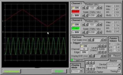
Android Oscilloscope

Here’s a 2-channel Oscilloscope for your Android phone. It uses a base module driven by a dsPIC for signal processing. From there, an LMX9838 Bluetooth module broadcasts the data to the phone so that the waveform can be displayed. [Yus] ported some Python code he had been using over to a set of Java and XML files in order to get it working on Android. This was actually the first time he worked with the SDK… we’d say he’s a quick learner. See it in action after the break.

Continue reading “Android Oscilloscope”

40 MSPS Digital Oscilloscope

If you can fabricate single-sided circuit boards at home you can build this digital oscilloscope. It uses mostly through-hole components with just a couple of surface mount chips to contend with. An ATmega162 handles the hardware end of things with a CPLD used to manage the sampling rate. Data is displayed on a 240×128 LCD display which will be the most expensive component to acquire. It’s still a lot cheaper than buying a commercially available oscilloscope, even if you get a base model and hack it to unlock all the features.

[Thanks Juan]

Update: 50MHz To 100Mhz Scope Conversion

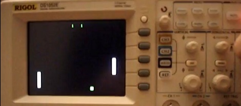
Changing this 50MHz Rigol oscilloscope into its larger, more expensive brother just became quite a bit easier. When we originally looked at this hack it required pulling some capacitors off of the board. Now all it takes is three commands over a serial terminal connection.

Take a look at the walk through video after the break. You’ll see that there’s one chip that needs to be setup differently to change the functionality. Removing capacitors was actually changing the commands sent to initialize that chip at power-up. Now you can just change the model number and one letter of the serial number via a terminal and the firmware will recognize this as the more expensive DS1102E.

Continue reading “Update: 50MHz To 100Mhz Scope Conversion”

50MHz To 100Mhz Scope Conversion

[Ross] is the proud owner of a 50 MHz Rigol DS1052E oscilloscope. He’d like to have the 100 MHz version but the $400 difference in price puts it out of his reach. After some extensive poking around on the PCB and pouring over datasheets, he managed to reverse engineer the design and upgrade to a 100 MHz version. This is as easy as desoldering one capacitor to deactivate a high-pass filter present in the lesser model of scope, unlocking the faster potential of its bigger brother.

USB Oscilloscope

Here’s a USB oscilloscope project from a few years back. It’s easy to build on a single-sided PCB and very cheap because it uses just a handful of parts. At the center, an ATtiny45 microcontroller uses its ADC capabilities for the two traces and also handles the USB connectivity. The internal oscillator is used and trimmed up for accuracy by referencing the USB clock. On the PC side of things, a program written in C# displays the data coming over the serial bus. Quick, small, and useful; a schematic, board layout, firmware, and PC software sources are all available for download.

[Thanks Shri]

Oscilloscope Doubles As A Serial Terminal

PC-based USB oscilloscopes are fast becoming all the rage. [Matt Sarnoff’s] Terminalscope takes the reverse approach, adapting an oscilloscope into a full serial terminal. You may have seen something similar before in the Dutchtronix/SparkFun O-Clock, but [Matt’s] project goes one further by adding a PS/2 keyboard port for full bidirectional serial communication, and with much sharper display resolution to boot.

The mostly VT-100 compatible Terminalscope is built around two AVR microcontrollers: an ATmega328P runs full-tilt to generate the video signal and handle serial I/O, while an ATtiny45 handles keyboard input to avoid interrupting the ’328’s duties. Rather than vector trace each character, a raster-scanning approach is used: the beam follows a fixed X/Y path (like a television), while modulating the Z input (beam intensity) to form an image. The device can be connected to a PC via serial port or USB-to-TTY adapter, or directly to another microcontroller to debug serial output.

We recently showed an oscilloscope being used as a multichannel digital logic display. The Terminalscope provides yet another use for this essential bench tool and could nicely round out a “poor man’s” testing setup. The schematic and full source code are available for download.

Use An Analog Oscilloscope To Display Digital Logic

[Mike Bradley] wanted to use his oscilloscope to display 8 channels of digital signals. Alas, the analog unit didn’t have this capability. Not to worry, he threw together an adapter module that does the trick. Using a PIC 18F26K20 microcontroller he inputs four or eight channel digital logic (at 5V) and filters the output to an analog signal that the oscilloscope can interpret. What you see in the photo above is the result.