Tiny OLED O-scope Fits On A Breadboard

[youtube=http://www.youtube.com/watch?v=UfAkdd9kXNY&w=470]

With a surplus of 3D printers at this year’s Maker Faire, it’s really surprising to see the most talked about tool among the makers is a simple oscilloscope.

[Gabriel Anzziani]’s Xprotolab is an extremely small oscilloscope, function generator, logic analyzer, and general 128×64 OLED display is the perfect addition to your next prototyping project. With its breadboard friendly format and USB output, it will dutifully serve as a 200kbps oscilloscope, 8 channel logic analyzer, or as seen in the video above, the perfect interface for a Wii Nunchuck or just a simple digital Etch-a-sketch.

In the video above the fold [Gabriel] shows off the functions of his tiny, if somewhat limited, OLED oscilloscope.
Scratch-built RFID Reader

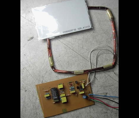
We never bought an RFID reader because it seems too simple to be all that much fun. But [Abdullah] really caught our eye with his latest project. It’s an RFID reader built from discrete parts, and that’s an adventure we can get behind!

His write-up dives right into the theory of the device. He wrapped his own coil, which measure about one microhenry, then shares an equation used to calculate the appropriate capacitor pair for it. This is fed by a 125 kHz oscillator and works as the most basic reader. In practice this needs more components for rock-solid operation and he quickly moves to a marginally more complicated circuit which still does exactly the same thing.

He is now able to detect RFID tag data by reading this circuit with an oscilloscope. But the signal is very very weak. The rest of the post focuses on how to best utilize an OpAmp to increase signal quality and on/off time.

If you’re looking to recreate his reader [Abdullah] included a Kicad schematic and board layout.

EMF Oscilloscope Probe

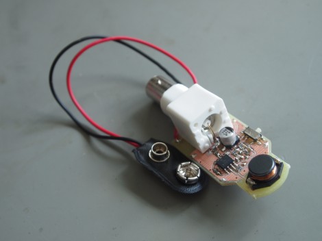
[Tuomas Nylund] wanted a way to visualize the electromagnetic fields (EMF) around him. He figured the oscilloscope was the tool best suited for the task, but he needed a way to pick up the fields and feed them into one of the scope’s probes. He ended up building this EFM probe dongle to accomplish the task.

He admits that this isn’t much more than just an inductor connected to the probe and should not be used for serious measurements. But we think he’s selling himself short. It may not be what he considers precision, but the amplification circuit and filtering components he rolled into the device appear to provide very reliable input signals. We also appreciate the use of a BNC connector for easy interface. Check out the demo video after the break to see the EMF coming off of a soldering station controller, from a scanning LCD screen, and that of a switch-mode power supply.

Continue reading “EMF Oscilloscope Probe” →

Android Oscilloscope Built From Parts Just Lying Around

So you need to debug a circuit and you don’t have an oscilloscope. That’s not a problem thanks to [retronics] $0 Android oscilloscope, made with parts he just happened to have lying around.

The heart of every modern oscilloscope is the ADC – the chip that takes analog input and outputs a digital signal. Every Android device has one of these converters connected to the microphone port. All [retronics] needed to do was solder up a 3mm headphone jack, wire in a few resistors, and attach a pair of alligator clips. After installing an oscilloscope app, [retronics] had a half decent ‘scope.

Yes, this is truly a poor man’s oscilloscope, and [retronics] probably won’t be debugging high frequency RF circuits with his Android microphone jack anytime soon. Low frequency stuff such as audio is where this ‘scope really excels; even more so if a small preamp is thrown into the mix.

You can check out [retronics]’ build after the break. Sure, it’s not something for precise and calibrated measurement, but sometimes you only need a tool that will do the job.

Continue reading “Android Oscilloscope Built From Parts Just Lying Around” →

Raspberry Pi Controlled Tank Goes Deeper Than You Might Think

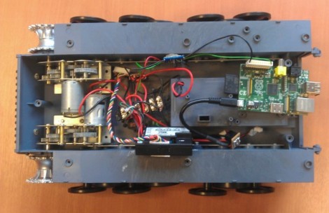
This remote control tank now takes its orders from a Raspberry Pi board. Well, actually it’s taking orders from commands pushed to the RPi board via SSH. The control scheme works out quite well. Using a low-profile WiFi dongle the RPi automatically connects to the wireless network when it is powered on. This makes it a snap to SSH into the device, and a more user-friendly controller will put a nice front-end into play at some time in the future.

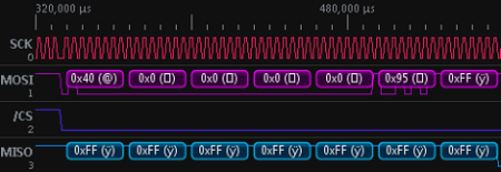
But the real meat and potatoes of the hack comes in getting the RPi to talk to the tank’s circuitry. Just getting the Heng Long Tiger I remote control tank apart proved to be a ton of work as the treads need to be removed to do so and there’s a lot of screws holding it together. Instead of just replacing all of the control circuitry [Ian] wanted to patch into the original controller. To do so he spent a bit of time analyzing the signals with an oscilloscope and discovered that commands were coming in a Manchester encoded format. He established what various packets were doing, used a transistor to protect the GPIO pin on his board, and now has full control of the Tank. The final part of the hardware alteration was to power the RPi from the Tank’s battery.

After the break you can catch a demo of the reassembled tank sporting its new wireless controller.

Continue reading “Raspberry Pi Controlled Tank Goes Deeper Than You Might Think” →

Turning An Oscilloscope Into A Logic Analyzer

Sooner or later, you’re going to need a logic analyzer. If you don’t have a Bus Pirate or Logic Sniffer lying around, [Joonas] has a great MacGyverism that turns an oscilloscope into the simplest logic analyzer ever.

The basic premise of the build is tying four digital lines to the analog input of an oscope. This is done with a 74HC126 buffer that provides a high impedance input for the logic probes and outputs the four-bit status of each logic channel. With a few resistors in an R-2R network, the state of four digital lines can be easily read.

[Joonas] included the source code to turn his Picoscope 2000 into a logic analyzer, but there’s no reason why this couldn’t be done with any digital scope that has a serial output. Not bad for a very, very simple logic analyzer – just one chip and a handful of resistors – that costs less than $5.

Watch A Shop Tour Through The Screen Of An Oscilloscope

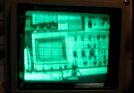
[Alan] posted a video tour of his electronics shop, but you’ll be viewing it through the green screen of an oscilloscope. The image above is a video camera filming a scope screen which displays the image of…. an oscilloscope (insert your own Yo Dawg meme here). But first he shares the technique he uses to display composite video on an oscilloscope screen.

The first three minutes of the video after the break are devoted to the video display hack. He starts with a glimpse of the breadboard circuit which takes the composite video signal and provides the necessary X, Y, and Z input signals to the scope to perform like this. He then walks through each portion of the schematic, which is based on an LM1881 video sync separator chip. The horizontal and vertical sync signals are separated by this chip, then filtered to produce ramp voltages for each to drive X and Y. The Z-axis is fed through a simple inverter circuit; Bob’s your uncle and your oscilloscope is now a TV monitor.

Of course this is not the first time this has been done. But we loved [Alan’s] presentation, and thought the shop tour was a fun way to finish off the video.

Continue reading “Watch A Shop Tour Through The Screen Of An Oscilloscope” →