Developing A Better Way To Control 10,000 LEDs

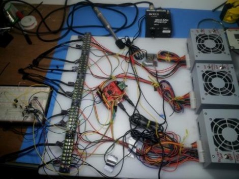
The SoundPuddle project drives thousands of LEDs based on audio input. The team is working on a replacing the controller for this wire-filled setup with something more robust. They took the mess seen above to the Apogaea Festival and were plagued by loose wires and unreliable communications due to noise and interference. The aim of the new system is to reliably control up to 10,000 LEDs.

The red PCB seen at the center of the rats-nest is a Papilio FPGA board. They still want to use it to drive the installation, but a new hardware interface is necessary. The solution is to design what they call a megawing (wings are to Papilio as shields are to Arduino).  The LEDs will be in RGB strip form, so one of the requirements is to supply enough connectors to drive 16 channels of SPI devices. The wing will also include the 48V power source and connectors for the condenser microphone that serves as an input for the SoundPuddle. There are also two other options for audio input, one via a Bluetooth module (which can double as a control device) and the other via MIDI.

After the break you can see a lighting demo. Be ready with the volume controls as most of the sounds used in the test are quite annoying.

Continue reading “Developing A Better Way To Control 10,000 LEDs”

Building An Arduino Chiptunes Project Inside An FPGA

From time to time we find ourselves in the mood for some Chiptunes. You know, the music that accompanied all of the best 8-bit console games? These days there are a lot of projects that use the audio chips of yore to recreate the sounds, but you’re always faced with the issue of sourcing those parts. [Jack Gassett] took some inspiration from one of those projects, but solved the rare hardware dilemma by building his own Chiptunes MIDI device in an FPGA.

He saw one of our features on an Arduino controlled YM2149 programmable sound generator. He realized that you can already find FPGA libraries out there that mimic this sound generation hardware, and he’s already done extensive work with an Arduino soft processor. Why not combine the two?

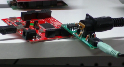
He’s using a Papilio FPGA with a wing that includes a MIDI connector and audio-out jack. As you can hear in the clip after the break this sounds just like the real thing. And he’s got plans to roll as many different types of sound generating chips into the mix as possible. You know, one FPGA synth to rule them all.

Continue reading “Building An Arduino Chiptunes Project Inside An FPGA”

Conway’s Game Of Life In HD

We’re going to have to take [Mike’s] word for it that he built Conway’s Game of Life with high-definition video output. That’s because this screenshot is his only proof and it looks a bit fuzzy to us. But we are interested in the project which used an FPGA to generate a 1080p VGA output of the classic programming challenge.

One of the biggest benefits of using an FPGA for this application is the hardware’s parallel processing ability. For every frame of the game, the area around each living cell must be analyzed to produce the next evolutionary step. Most of the time this means processing all of the pixels in the playing area, which is the case here. [Mike] is using VHDL to program a Papilio Plus which has a Spartan 6 chip on it. He separated his code into the different components when writing about it. This makes it easy to find the chunks relating to the game if that’s what you’re interested in. If you just want to see how he implemented the VGA interface that’s well documented as well.

If you’re not familiar, Conway’s Game of Life has simple rules regarding when a cell will live, die, or be reborn. As [Mike] points out, every programmer should give it a shot at some point. We’ve seen many iterations from the very large to the very small.

$10 Camera Module For Your Next FPGA Project

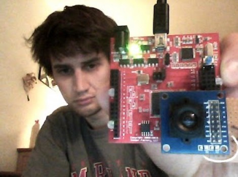
Here is [Voelker] showing off his FPGA-based camera hardware. He picked up an ov7670 camera on eBay for about $10 and set to work pulling pixels and processing the images. He’s now able to grab thirty frames per second and push them to his own Java display application. He’s using the Papilio board and if you want to give this a try yourself you might be able to snag a free breakout board (wing) for the unit.

[Voelker’s] approach is to grab each frame, and get it ready for quick serial transmission. The incoming frames are at 640×480 resolution. He scales that down to 80×60 and transmitted at 3M baud. The hardware resources used are actually quite light-weight. He wrote his own modules for transfer and photo processing using very little RAM for downscaling and one 128 byte buffer for data transmission. It sounds like he plans to use the camera to view and detect a line to create his own line-following robot.

Wondering where you’ve seen the ov7670 module before? It’s the part used on the TRAKR robot.

Fractal Viewer Can Zoom And Enhance Like On CSI

This fractal viewer is a great way to get your feet wet with Field-Programmable Gate Arrays. The project will give you some experience working with video output, user input, and a whole bunch of math and memory management. [Hamster] built it using the Papilio Plus board which hosts a Spartan 6 FPGA. This continues his odyssey into the realm of hardware design; part of which we looked at back in December.

The arcade Megawing for the dev board gives him easy access to the controls needed to scroll and zoom on the fractal design. Calculations to generate the shape are being run at 240 MHz, with the VGA output running at 80 MHz. The device has enough horse power and SRAM to show an 800×600 pixel output with a 60 Hz refresh rate.

We really liked the logic diagram that [Hamster] drew up when planning how the calculations would be handled. It’s not overly complex, but it took us a while to conceptualize how everything fits together. It’s certainly an improvement from his last attempt as we couldn’t make heads or tails out of that flow chart.

If you’re just interested in the pretty shapes and colors there’s a demo embedded after the break.

Continue reading “Fractal Viewer Can Zoom And Enhance Like On CSI”

Simulating VHDL Of An AVR8 Soft Processor

Okay, now we’re beginning to feel a bit like [Alice]. This tutorial shows you how to simulate VHDL code. This code is intended to run on an FPGA and includes a software-only version of the AVR 8-bit microcontroller core. Essentially, you’ll simulate VHDL code that simulates AVR hardware. Wrap your mind around that!

The code is intended to run on a Papilio Field Programmable Gate Array development board. We saw an early version of this board running the AVR8 core about a year ago. However, you don’t need to have any hardware to follow along and recreate this simulation yourself. It might be a great way to get your feet wet with FPGA programming before making that first hardware buy. Five different screencasts take you through the process of getting the AVR8 code, using an altered Arduino IDE for it, setting up a free version of Xilinx ISE to run the simulation, then setting it free and interpreting the data that the simulator spits out the other end.