One of the first things anyone with an interest in electronics learns is the resistor colour code. The colour of the first band reveals the first figure, the second the subsequent figure, and the third a power-of-ten multiplier. At first you learn these colours, but eventually you just recognise the values through familiarity. You don’t have to think about multipliers when you see orange-orange-red, you just know that it’s a 3K3 resistor.
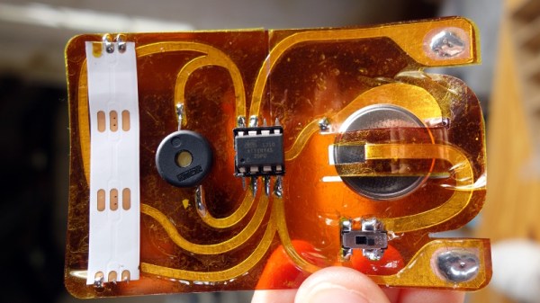
[Plusea] has come up with an entertaining interface for an ohmmeter, which instead of displaying the resistance on an LCD or a meter shows it as the colours of the code, via a set of addressable LEDs. The work is done by an ATtiny85 microcontroller, and the whole thing is mounted on a flexible PCB (fabrication of which is itself interesting, placing cut copper traces on a sheet of kapton and covering with a second kapton layer cut to be the solder mask). There is even a clever integration of a CR2032 battery holder from the PCB itself, though they admit that it could be made more compact with the use of SMD components instead of through-hole.
The write-up and associated photo album tells us a lot about the project, but is missing a crucial detail: a shot of it working. We’ll give them the benefit of the doubt on that front though, because we like the idea and its execution.
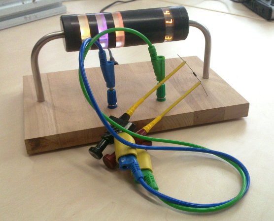
Strangely, this isn’t the first ohmmeter to use the resistor colour code in this way, we’ve previously brought you one featuring a light-up giant resistor.