What’s a hacker to do to profess his love for his dearest beloved? [Nitesh Kadyan] built his lady-love this awesome LED pendant – the LED BLE Hearty Necklace Badge.
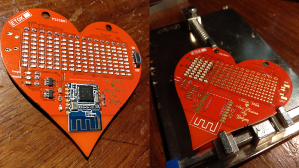
The hardware is pretty vanilla by today’s hacker standards. An ATMega328p does most of the heavy lifting. An HM-11 BLE module provides connection to an Android mobile app. Two 74HC595 shift registers drive 16 columns of red LEDs and a ULN2803 sinks current from the 8 rows. The power section consists of a charger for the 320mAh LiPo and an LDO for the BLE module. All the parts are SMD with the passives mostly being 0603, including the 128 LEDs.
[Nitesh] didn’t get a stencil made for his first batch of boards, so all the parts were painstakingly soldered manually and not in a reflow oven. And on his first board, he ended up soldering all of the LED’s the wrong way around. Kudos to him for his doggedness and patience.
The Arduino code on the ATmega is also quite straightforward. All characters are stored as eight bytes each in program memory and occupy 8×8 pixels on the matrix. The bytes to be displayed are stored in a buffer and the columns are left shifted fast enough for the marquee text effect. The Android app is built by modifying a demo BLE app provided by Google. The firmware, Android app, and the KiCAD design files are all hosted on his Github repository.
[Nitesh] is now building a larger batch of these badges to bring them to hillhacks – the annual hacker-con for making and hacking in the Himalayas. Scheduled for later this month, you’ll have to sign up on the mailing list for details and if you’d like to snag one of these badges. To make it more interesting, [Nitesh] has added two games to the code – Tetris and Snakes. Hopefully, this will spur others to create more games for the badge, such as Pong.
 Disco Floor’s are passé. [dennis1a4] turned them upside down and built an awesome
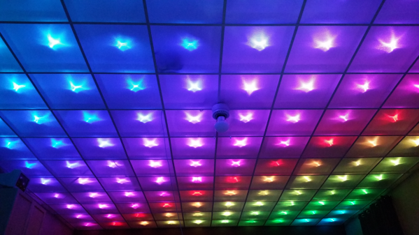
  The hard part was wiring up all of the 160 LED pixels. Instead of mounting the 5050 SMD LED’s on PCBs, [dennis1a4] wired them all up “dead bug” style. Each pixel has one LED, a 100nF decoupling capacitor, and 91 ohm resistors in series with the Data In and Data Out pins – these apparently help prevent ‘ringing’ on the data bus. Check the video for his radical soldering method. Each SMD LED was clamped in a machine shop vice, and the other three parts with their leads preformed were soldered directly to the LED pins.


