Reverse Engineering An ST-Link Programmer

We’re not sure why [lujji] would want to hack ST’s ST-Link programmer firmware, but it’s definitely cool that he did, and his writeup is a great primer in hacking embedded devices in two parts: first he unpacks and decrypts the factory firmware and verifies that he can then upload his own encrypted firmware through the bootloader, and then he dumps the bootloader, figures out where it’s locking the firmware image, and sidesteps the protection.

[lujji]’s project was greatly helped out by having the firmware’s encryption keys from previous work by [Taylor Killian]. Once able to run his own code on an intact device, [lujji] wrote a quick routine that dumped the entire flash ROM contents out over the serial port. This gave him the bootloader binary, the missing piece in the two-part puzzle.

If you’ve ever broken copy protection of the mid-1990’s, you won’t be surprised what happened next. [lujji] located the routine where the bootloader adds in the read protection, and NOPped it out. After uploading firmware with this altered bootloader, [lujji] found that it wasn’t read-protected anymore. Game over!

We glossed over a couple useful tips and tricks along the way, so if you’re into reversing firmware, give [lujji]’s blog a look. If you just want a nice ARM programmer with UART capabilities, however, there’s no reason to go to these extremes. The Black Magic Probe project gives you equal functionality and it’s open source. Or given that the official ST-Link programmers are given away nearly free with every Nucleo board, just buying one is clearly the path of least resistance. But a nice hack like this is its own reward for those who want to take that path. Thanks, [lujji] for writing it up.

Reverse Engineering ST-Link/V2 Firmware

reverse-engineering-stlink-v2

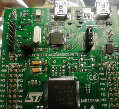
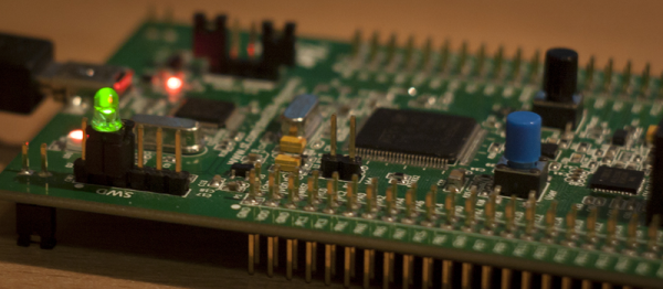
The chip seen just above the center of this image is an ARM Cortex-M3. It provides the ability to interface and program the main chip on the STM32F3 Discovery board. The protocol used is the ST-Link/V2 which has become the standard for ST Microelectronics development boards. The thing is, that big ARM chip near the bottom of the image has multiple UARTs and bridging a couple of solder points will connect it to the ST-Link hardware. [Taylor Killian] wanted to figure out if there is built-in firmware support to make this a USB-to-serial converter and his path to the solution involved reverse engineering the ST-Link/V2 firmware.

The first part of the challenge was to get his hands on a firmware image. When you download the firmware update package the image is not included as a discrete file. Instead he had to sniff the USB traffic during a firmware update. He managed to isolate the file and chase down the encryption technique which is being used. It’s a fun read to see how he did this, and we’re looking forward to learning what he can accomplish now that’s got the goods he was after.

Hacked ARM Dev Board Gives You Two For The Price Of One!

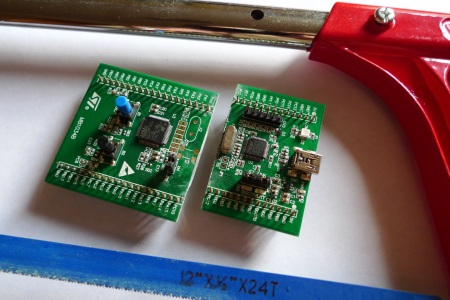
[Matt Evans] took a closer look at the popular (and cheap) STM32F0 Discovery development board and realized he could get a second board out of the deal.

The Discovery board is designed to advertise ST Microntroller’s STM32F0 microchip; which with 8k RAM, 64K Flash, a bunch of peripherals,  48MHz clock, and a low price is a great chip. Though, they needed a way to program the STM32F0. To do this they added a second, more powerful, chip to the board as an interface. The STM32F103, with 20k RAM, 64K flash, and a 72MHz clock speed. [Matt] summoned genius, and simply sawed the board in half using a hacksaw.

Of course the caveat to all this is that you need a working Discovery board, or at least a working ST-LINK programmer, at the end of the day, to get any use out of your creation. Since the boards are so cheap though, it shouldn’t be a problem to buy two.

New STM32 Discovery Board Can Now Be Programmed On Linux

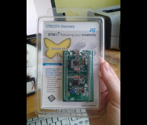
Last Wednesday I posted a video review of the new STM32F0-Discovery board which is built around an ARM Cortex-M0 chip. I speculated that it should work with the open source project aimed at programming these discovery boards. I tested it out and a connection could be made, but no code could be flashed. So I spent a few hours over the weekend and added support.

My updates are already in the stlink repository. After cloning the code, you can use three commands to compile the software (./autogen.sh, ./configure, make). That’s assuming you have all of the necessary dependencies (I had to install libusb-1.0-0-dev) and that you add the udev rule suggested in the documentation (also found in the repository). The program st-util connects to the board and provides a listening port for an ARM debugger (I’m using arm-none-eabi-gdb from CodeSourcery G++ Lite).

When I first started testing, the chip id was reporting as 0. It turns out the register address polled for this information was wrong. After finding that in the almost-900 page reference manual I went through the painstaking process of finding the hex values necessary to properly memory map the device. From there I also updated the blink example to generate an ELF file compatible with the Cortex-M0 chip. So out of the gate you should be able to use an ARM cross compiling toolchain to compile the example, connect to the board with this utility, then use the debugger from the toolchain to connect and flash that example to RAM.

There’s lots more to be done. To fully utilize the chip it is necessary to use a startup file and linker script when compiling. I’ve done nothing in this area, but I hope to work on some tutorials as I get further along. Of course if you have your own successes developing for this board using a Linux machine we want to hear about it!