C64 Runs On STM32F429 Discovery

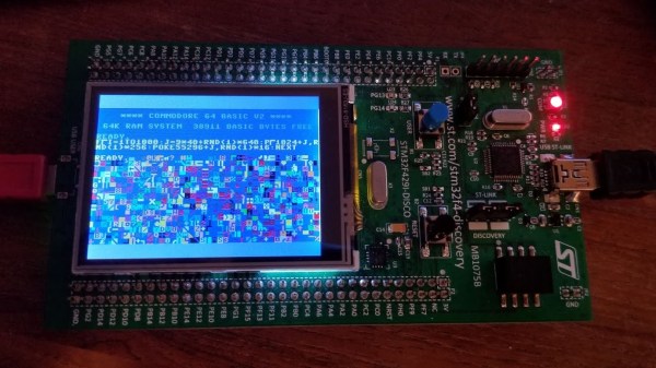
There have been various reincarnations of the Commodore C64 over the years, and [Dave Van Wagner] has created one that can run on an STM32F429ZI Discovery development board. These dev boards have been around quite a few years and feature a 2.4 inch color TFT LCD in addition to the typical I/O circuitry, and are a pretty good value — [Dave] says they currently sell for under $30 through distribution.

The project began earlier this year when [Dave] set out to write a command line program in C# that emulated C64 Basic. He had written a 6502 emulator many years earlier, but had not tested it. [Dave] went on a programming binge in March and got it up and running over a very long weekend. He subsequently decided to add support for VIC-20, TED, and PET as well.

Even though [Dave] says C# is a beautiful language, he subsequently ported the program into C (an ugly language?) in order to run on the Discovery board, swapping the command line terminal interface for real LCD video and a USB keyboard. There’s also an Arduino version (terminal interface only). It runs about 15% slower than a real C64, and there are some limitations still like no SID. But overall, this is a great project and a low-cost way to emulate a C64 in an embedded format. If you want to explore further, here is the Mbed project for the STM32F429, and you can find the Arduino and C# versions on his GitHub page. You may remember [Dave] from the C128 video hack we wrote about last year.

Using DMA To Drive WS2812 LED Pixels

It’s pretty well known by now that the LED pixel hardware which is starting to be commonplace, both WS2811 and WS2812, needs pretty strict timing in order to address them. There are libraries out there which mean almost no work on your part, but that’s no fun. [Elia] started looking into what it takes to drive the hardware, trying out a few 8-bit micros before moving to 32-bit with the help of an STM32VL Discovery Board. The move to a beefier processor brings a lot of speed, but why bit bang everything? He came up with a way to use the PWM and DMA features of the chip to drive the LEDs.

DMA is the Direct Memory Access unit that allows you to change the values being sent to the pixel without interrupting the processor. This is done by pre-loading the data at a memory location. This buffer is automatically read by the DMA unit — its values are used to set the PWM timer compare trigger in order to send out logic values show in the diagram above.

If you do want to delve further into this topic here’s a collection of techniques for driving the WS2811.

Continue reading “Using DMA To Drive WS2812 LED Pixels”

Taming STM32 Discovery Boards For Regular Use

taming-discovery-boards

We think [Karl Lunt] has a point when he says that the STM32 Discovery Boards are cool and inexpensive, yet not hobby friendly. But it’s nothing that a little big of creativity can’t solve. Above are pictured three of the hacks he used to tame the Discovery boards.

The first is the addition of a microSD card adapter. He soldered wirewrap wire to each of the contacts on the adapter. He recommends a low iron setting to make sure you don’t melt the plastic adapter housing. He then used double stick foam tape to adhere it to the bottom of the dev board. The other ends of the wire are wrapped around the appropriate pins on the dual-row pin header. Similarly, the UART3 connections are broken out from the pin headers to that white quick connect socket. This lets him access serial data without having to solve the USB issues that were vexing him.

Finally, he made his own daughter board to break out the dual row headers into screw terminals. We’ve been hit with problems interfacing hardware with the board’s native connections — jumpering to IDE cables just never worked reliably. This breakout board not only makes it simple, but organizes the pins into groups based on their alternate functions.

Do you remember seeing the hacksaw version of this Discovery board which gives you two dev boards for the price of one?

Impressive Dev Boards For Your STM32 Dev Boards

stm32-discovery-breakout-boards

It seems there are a lot of people who have the same complaint about the STM32 Discovery boards; it can be difficult to add external hardware to them. Don’t get us wrong, we appreciate all of the pins being broken out (as opposed to the Stellaris Launchpad which we think has too few available). Here’s [Scot Kornak’s] solution to the problem. He created three different baseboards which the STM32 Discovery plugs into. Each is for a different model of dev board: the VL, F3, and F4. But he also thinks the baseboard we saw in this other project is a good choice for an F4 solution.

These large PCB add-ons bring functionality in two different ways. The first is by using expandable ports for drop in modules like serial communications connectors or Analog/SPI/I2C modules. For us, the second method is the most desirable. He routes each GPIO port to a 2×8 header and uses IDC cables (rainbow cable in these images) to connect them to a breadboard. Seeing this makes us wish STM had used discreet clusters of 16 pins instead of those super long dual pin headers.

Classic Game Of Snake On An ARM Controller

Every now and again we take a break from looking at all of your awesome projects and get to work on our own. I thought I’d take a minute to show off my game of Snake. It’s a classic that I remember playing on a graphing calculator (TI-83) back in high school. I had never written my own version and decided it would be a good reason to spend some more time on the ARM platform.

The dev board I’m using is the STM32 F0 Discovery board. Once I had a usable template for compiling the code on a Linux box everything else just started to fall into place. The screen is from a Nokia 3595. Several years back I cut off the keypad and made a breakout board for it. It’s pretty dim but it’s small and uses SPI so it tends to be my go-to display for prototyping. But I did get my hands on an SSD1289 TFT screen (after writing about this project) for about $16 and I’ve had some success with that. It uses a parallel interface so it’s not as easy to hook up and I’ve had some crosstalk issues when running at 24 MHz.

But I digress. Check out the demo video of my simple game after the break. There are more details about my programming choices at post link above. You will see this hardware again soon. I’m working on an On Chip Debugging primer and these ARM dev boards are perfect for it!

Continue reading “Classic Game Of Snake On An ARM Controller”

New STM32 Discovery Board Can Now Be Programmed On Linux

Last Wednesday I posted a video review of the new STM32F0-Discovery board which is built around an ARM Cortex-M0 chip. I speculated that it should work with the open source project aimed at programming these discovery boards. I tested it out and a connection could be made, but no code could be flashed. So I spent a few hours over the weekend and added support.

My updates are already in the stlink repository. After cloning the code, you can use three commands to compile the software (./autogen.sh, ./configure, make). That’s assuming you have all of the necessary dependencies (I had to install libusb-1.0-0-dev) and that you add the udev rule suggested in the documentation (also found in the repository). The program st-util connects to the board and provides a listening port for an ARM debugger (I’m using arm-none-eabi-gdb from CodeSourcery G++ Lite).

When I first started testing, the chip id was reporting as 0. It turns out the register address polled for this information was wrong. After finding that in the almost-900 page reference manual I went through the painstaking process of finding the hex values necessary to properly memory map the device. From there I also updated the blink example to generate an ELF file compatible with the Cortex-M0 chip. So out of the gate you should be able to use an ARM cross compiling toolchain to compile the example, connect to the board with this utility, then use the debugger from the toolchain to connect and flash that example to RAM.

There’s lots more to be done. To fully utilize the chip it is necessary to use a startup file and linker script when compiling. I’ve done nothing in this area, but I hope to work on some tutorials as I get further along. Of course if you have your own successes developing for this board using a Linux machine we want to hear about it!

ARM Programming Primer; Getting The USART Running

We find it interesting that PIC and AVR programming is very common in hobby electronics but ARM doesn’t have nearly the same foothold. This is partly because there’s a knowledge barrier involved with making the transition (the other part is probably the lack of DIP packaged chips). But if you’ve worked with 8-bit microcontrollers you can certainly make the jump into the 32-bit realm. Here’s a great opportunity to get your feet wet. This guide will show you how to get the USART on an STM32 Discovery Board working, which makes it easy to get feedback about what’s going on in your program.

One difference you’ll notice when moving to ARM microcontrollers is that there is almost always a library bundle available from the manufacturer which includes all of the functions you need for hardware control (USART, USB, Ethernet, ADC, etc.). That’s the case here, so simply including the USART library makes it a snap to finish the rest of the program. Once you hook up your communications hardware (an FTDI cable in this case) just use the library initialization functions, followed by the send and receive commands and you’ll be pushing messages to a computer terminal in no time.

If you’re trying to use the STM32 Discovery Board with a Linux box here’s a shove in the right direction.