Diaphragm Air Engine

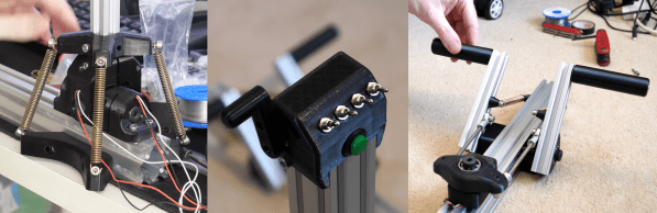
One of the tricky parts of engineering in the physical world is making machines work with the available resources and manufacturing technologies. [Tom Stanton] has designed and made a couple of air-powered 3D printed engines but always struggled with the problem of air leaking past the 3D-printed pistons. Instead of trying to make an air-tight piston, he added a rubber membrane and a clever valve system to create a diaphragm air engine.

This GIF is worth 115 words

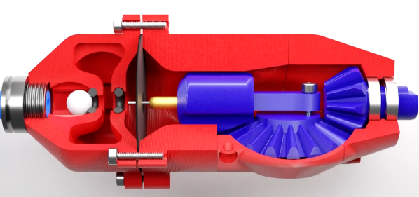
A round rubber diaphragm with a hole in the center creates a seal with the piston at the top of its stroke. A brass sleeve and pin protrude through the diaphragm, and the sleeve seals create a plug with an o-ring, while the pin pushes open a ball which acts as the inlet valve to pressurize an intermediate chamber. As the piston retracts, the ball closes the inlet valve, the outlet valve of the intermediate chamber is opened, forcing the diaphragm to push against the piston. The seal between the piston and diaphragm holds until the piston reaches its bottom position, where the pressurized air is vented past the piston and out through the gearbox. For full details see the video after the break.

It took a few iterations to get the engine to run. The volume of the intermediate chamber had to increase and [Tom] had to try a few different combinations of the sleeve and pin lengths to get the inlet timing right. Since he wanted to use the motor on a plane, he compared the thrust of the latest design with that of the previous version. The latest design improved efficiency by 366%. We look forward to seeing it fly! Continue reading “Diaphragm Air Engine”

Complete Flight Sim Controller Set With 3D Printing And Hall-Effect Sensors.

[Tom Stanton] has been playing Microsoft Flight Simulator a lot recently, and decided his old desktop joystick needed an upgrade. Instead of just replacing it with a newer commercial model, he built a complete controller system with a long joystick that pivots at floor level, integrated rudder pedals and a throttle box. You can see it in action after the break.

The throw of the joystick is limited by [Tom]’s legs and chair, with only 12° of travel in either axis, which is too small to allow for high resolution with a potentiometer. Instead, he used hall effect sensors and a square magnet for each axis, which gives good resolution over a small throw angle. The pivot that couples the two rudder pedals also makes use of a hall effect sensor, but needs more travel. To increase the size of the magnetic field, [Tom] mounted two magnets on either side of the sensor with their poles aligned. To center the rudder pedals and joystick, a couple of long tension springs were added.

The joystick (left) and rudder pedals (right) magnet configurations with a hall effect sensor.

A normal potentiometer was used in the throttle lever, and [Tom] also added a number of additional toggle switches and buttons for custom functions. The frame of the system is built with T-slot extrusions, so components can quickly moved to fit a specific user, and adjust the preload on the centering springs. All the electronic components are wired to an Arduino Micro, and thanks to a joystick library, the code is very simple.

At a total build cost of £212/$275 it’s certainly not what anyone would call cheap, but it’s less than what you’d pay for a commercial offering. All the design files and build details are linked in the second video if you want to build your own.

The flight sim controller builds are coming in thick and fast with the release of the latest MS Flight Simulator. With 3D printing you can augment an Xbox controller with a joystick and throttle, or just use tape and a few electronic components turn a desk drawer into a flight yoke.