The Saleae logic analyzer software is shown. One PWM channel is active, with values of 0x0001 displayed above the individual waveforms. On the right panel of the app, a trigger mode configuration panel is open for the simple parallel analyzer.

Simple Triggering For Saleae Logic Analyzers

Saleae logic analyzers seem to have it all: good sampling rates, convenient protocol decoding, and plenty of channels – but not a good way to set rising or falling-edge triggering. [James] found this rather inconvenient when debugging embedded devices, and shared a workaround that replicates these simple triggering modes.

Crucially, the logic analyzer’s software has a repeated triggering mode that fires when the protocol decoder detects a preset value. [James] used a clever trick to turn this into a rising-edge trigger: he set up a simple parallel analyzer, and set the signal in question as both the sampled channel and the clock signal. Since he wanted to detect the rising edge, he set the clock mode accordingly. Next, he loaded the simple parallel decoder’s trigger configuration and set it to detect a value of one, the value of a high signal. When he ran the simple parallel trigger, every rising edge of the input signal would trigger the clock to check for a high value on the line, in turn triggering the analyzer.

It’s also possible to set up a falling-edge trigger by selecting the falling-edge clock mode and setting the trigger mode to detect a value of zero. Setting up more complex triggers involving multiple channels is as simple as calculating the hexadecimal value of the desired state and setting the parallel decoder to trigger on that value. For example, if you want to trigger when one input is low and another is high, you can set the decoder to trigger on a value or one or two, depending on which order the inputs come in.

If all this makes you interested in Saleae logic analyzers, we’ve seen them used for everything from floppy disk preservation to signal generation. We’ve even reviewed their earliest model back in 2009.

Continue reading “Simple Triggering For Saleae Logic Analyzers”

Beyond The Basics: Exploring Exotic Scope Trigger Modes

Will Rogers once said that veterinarians are the best doctors because their patients can’t tell them where it hurts. I’ve often thought that electronic people have a similar problem. In many cases, what’s wrong with our circuits isn’t visible. Sure, you can visually identify a backward diode, a bad solder joint, or a blown fuse. But you can’t look at a battery and see that it is dead or that a clock signal isn’t reaching some voltage. There are lots of ways to look at what’s really going on, but there is no substitute for a scope. It used to be hard for the average person to own a scope, but these days, it doesn’t require much. If you aren’t shopping for the best tech or you are willing to use it with a PC, oscilloscopes are quite affordable. If you spend even a little, you can now get scopes that are surprisingly capable with features undreamed of in years past. For example, many modern scopes have a dizzying array of triggering options. Do you need them? What do they do? Let’s find out.

I’ll be using a relatively new Rigol DHO924S, but none of the triggering modes are unique to that instrument. Sometimes, they have different names, and, of course, their setup might look different than my pictures, but you should be able to figure it out.

What is Triggering?

In simple terms, an oscilloscope plots time across the X-axis and voltage vertically on the Y-axis. So you can look at two peaks, for example, and measure the distance between them to understand how far apart they are in time. If the signal you are measuring happens repeatedly — like a square or sine wave, for example — it hardly matters which set of peaks you look at. After all, they are all the same for practical purposes.

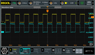
Pretty square waves all in a row. Channel 2 is 180 degrees out of phase (inverted). But is that all there is?

The problem occurs when you want to see something relative to a particular event. Basic scopes often have level triggering. They “start” when the input voltage goes above or below a certain value. Suppose you are looking at a square wave that goes from 0 V to 5 V. You could trigger at about 2.5 V, and the scope will never start in the middle of a cycle.

Digital scopes tend to capture data before and after the trigger, so the center of the screen will be right on an edge, and you’ll be able to see the square waves on either side. The picture shows two square waves on the screen with the trigger point marked with a T in the top center of the display. You can see the level in the top bar and also marked with a T on the right side of the screen.

What happens if there are no pulses on the trigger source channel? That depends. If you are in auto mode, the scope will eventually get impatient and trigger at random. This lets you see what’s going on, but there’s no reference. If you are in normal mode, though, the scope will either show nothing or show the last thing it displayed. Either way, the green text near the top left corner will read WAIT until the trigger event occurs. Then it will say T’D.

Continue reading “Beyond The Basics: Exploring Exotic Scope Trigger Modes”