Diagnose And Repair A Yaesu FT-7800 Ham Radio

Yaesu FT-7800 Ham Radio

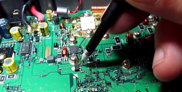
[Alan Wolke] aka [w2aew] was challenged to repair a friends Yaesu FT-7800 ham radio. This radio operates on two ham bands, 2 m VHF and 70 cm UHF. The complaint was that the 2 m side was not working but the 70 cm was transmitting fine. Alan started by verifying the complaint using a Bird watt meter with a 50 watt slug and terminating the signal into a 50 W dummy load. [Allen’s] bird meter is the type that has an RF sampler that can be connected to an oscilloscope for added signal viewing and validation.

After verifying that the radio was not working as described, Alan starts by glancing over the circuit board to look for any obvious damage. He then walks us through a block diagram as well as a circuit diagram of the FT-7800 radio before stepping us through the troubleshooting and diagnostics of radio repair. Even when he realizes he might have found the problem he still steps us through the remainder of his diagnostics. The skills and knowledge that Alan shares is extremely valuable to anybody looking to repair radios.

Spoiler alert. At the end of the first video he determines that the pin diodes near the final VHF output were bad. In the second video he reveals that he could no longer source these bad components. Through some clever evaluation of a more current Yaesu radio, [Allen] was able to find suitable replacement components. Lesson two ends with some surface mount solder rework tips as well as testing that the repair was successful.

And just in case you don’t know what a pin diode is, or is used for, Alan shares a third video covering just what this component is and does in a radio. You can follow the jump to watch all three videos.

Continue reading “Diagnose And Repair A Yaesu FT-7800 Ham Radio”

The Dish-o-Tron 6000 Is Back And Better Than Ever

dish_o_tron_6000_extreme

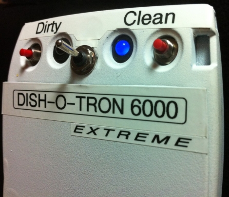
When designing a circuit on the bench, sometimes things work far better than they do in real life. [Quinn Dunki] learned this lesson over the last few months as she struggled with one of her recent creations, the Dish-o-Tron 6000. We featured the Dish-o-Tron back in April, and at that point things seemed to be working out well for [Quinn]. As time passed however, she found the device to be an unreliable power hog. Aside from eating through a battery every few weeks, it kept spontaneously switching states from ‘Dirty’ to ‘Clean’ and back. It was time to take the Dish-o-Tron back to the bench for some debugging.

The random status flip from ‘Dirty’ to ‘Clean’ was a relatively easy fix, and required a small capacitor between the set pin and ground to eliminate the electrical noise that was tripping things up. She nailed down the spontaneous ‘Clean’ to ‘Dirty’ flip to a stuck tilt switch, which she swapped out for a mercury-based model, making things far more reliable. She solved her battery problems by wiring in a 12v wall wart, which might not be any more energy efficient, but it does save her from swapping out batteries all the time.

It’s always nice to see how projects evolve over time, and how the inevitable bugs are worked out of an initial design.

Switched Mode Power Supply Repair Guide

switched_mode_power_supply_repaiir

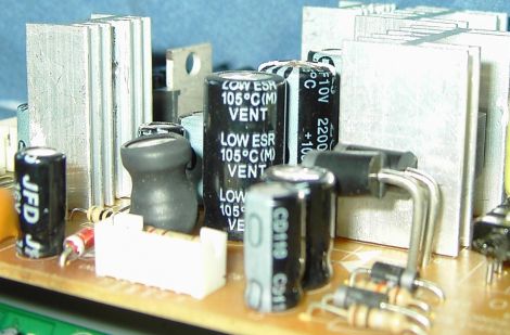
[Erich] spotted a broken DVD recorder at a local amateur radio meeting and decided to see if he could restore it to working order. While he was fortunate enough that someone labeled it as having a bad power supply, things aren’t always that easy. He gives a broad explanation as to how switched mode power supplies work as well as discusses some of the reasons these devices tend to fail. He identifies a few common components and areas that one should check while diagnosing a non-functioning power supply. While obvious bulging capacitors are easily identifiable, he discusses the need for an ESR meter and uses a kit-built model to test capacitors that do not have any visual signs of damage. While some of his walkthrough might be basic knowledge for readers who have experience in recapping circuit boards, it serves as a nice guide for those who are new to the world of electronics troubleshooting and repair.

Tools: Saleae Logic, Logic Analyzer

A logic analyzer records bus communications between two chips. If you’ve ever had a problem getting two chips to talk, or wanted to reverse engineer a protocol, a logic analyzer is the tool you need to spy on the bus.

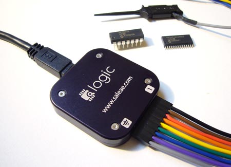
The Logic is a USB logic analyzer with eight channels and sampling rates up to 24MHz. Among hobby-level logic analyzers, the Logic has a good mix of features and decent sampling rates. We’ve been following Joe Garrison’s work on the Logic for a long time. If you’ve ever considered bringing a product to market, you can learn a lot from Joe’s blog that documents his development process.

When it debuted, the Logic was so popular that it was hard to buy one. It’s now widely available, and Saleae gave us one to try. Read our review below.

Continue reading “Tools: Saleae Logic, Logic Analyzer”