The Amiga 600 was in its day the machine nobody really wanted — a final attempt to flog the almost original spec 68000 platform from 1985, in 1992. Sure it had a PCMCIA slot nobody used, and an IDE interface for a laptop hard drive, but it served only to really annoy anyone who’d bought one when a few months later the higher-spec 1200 appeared. It’s had a rehabilitation in recent years though as a retrocomputer, and [LinuxJedi] has a 600 motherboard in need of some attention.
As expected for a machine of its age it can use replacement electrolytic capacitors, and its reset capacitor had bitten the dust. But there’s more to that with one of these machines, as capacitor leakage can damage the filter circuitry surrounding its video encoder chip. Since both video and audio flow through this circuit, there was no composite video to be seen.
The hack comes in removing the original chip rather than attempt the difficult task of replacing the filter, and replacing it with a different Sony chip in the same series. It’s nicely done with a connector in the original footprint, and a small daughterboard. The A600 lives again, but this time it won’t be a disappointment to anyone.
If you want to wallow in some Amiga history as well as read a rant about what went wrong, we have you covered.
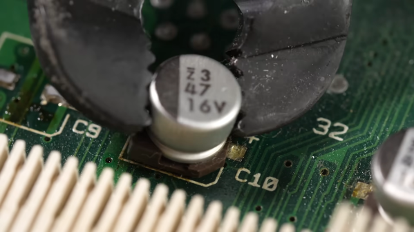
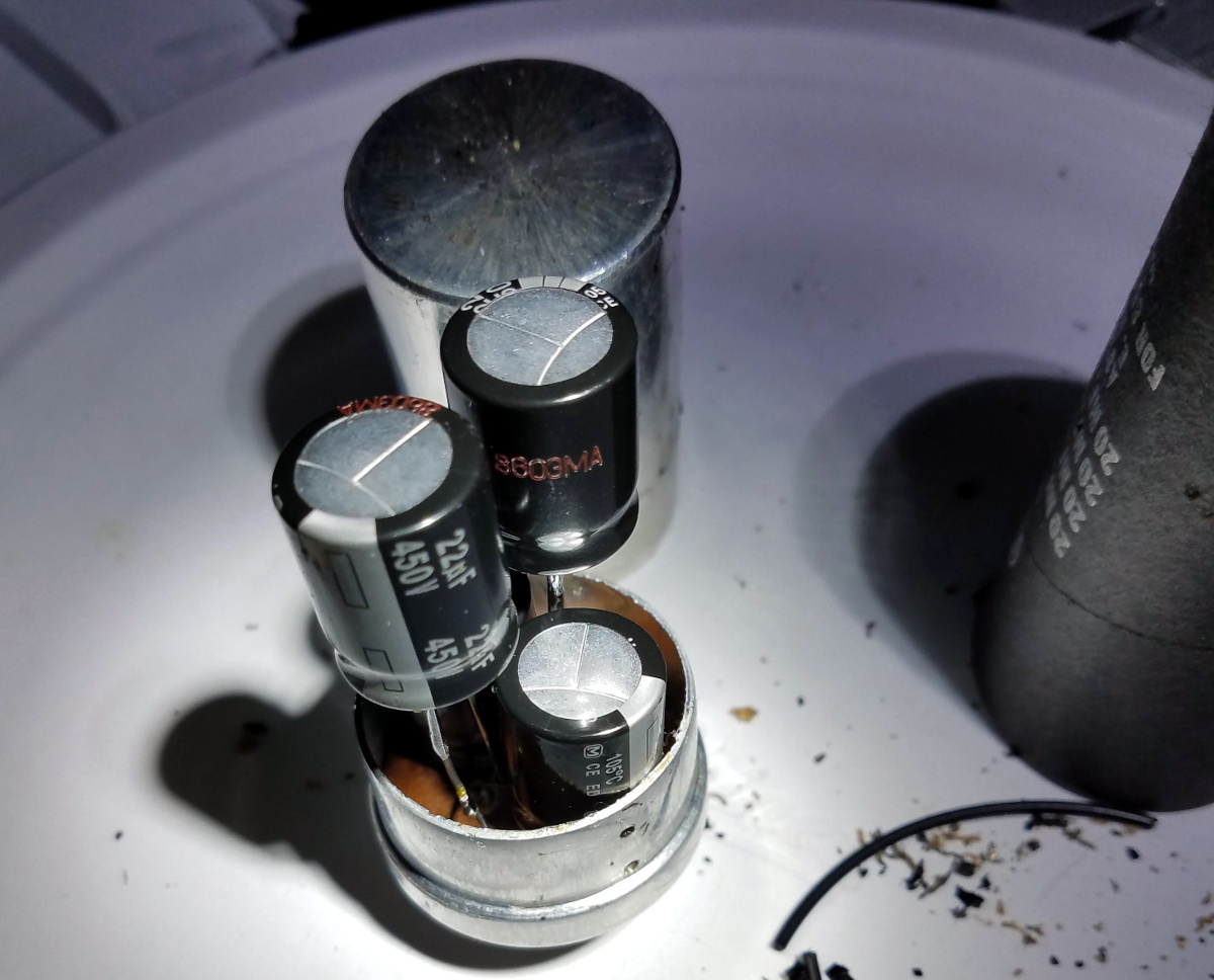
When you say “recapping” it conjures up an image of a dusty old chassis with point-to-point wiring with a bunch of dried-out old capacitors or dodgy-looking electrolytics that need replacement. But time marches on, and we’re now at the point where recapping just might mean removing SMD electrolytics from a densely packed PCB. What do you do then?
[This Does Not Compute]’s answer to that question is to try a bunch of different techniques and see what works best, and the results may surprise you. Removal of SMD electrolytic caps can be challenging; the big aluminum can sucks a lot of heat away, the leads are usually pretty far apart and partially obscured by the plastic base, and they’re usually stuffed in with a lot of other components, most of which you don’t want to bother. [TDNC] previously used a hot-air rework station and liberally applied Kapton tape and aluminum foil to direct the heat, but that’s tedious and time-consuming. Plus, electrolytics sometimes swell up when heated, expelling their corrosive contents on the PCB in the process.
As brutish as it sounds, the solution might just be as simple as ripping caps off with pliers. This seems extreme, and with agree that the risk of tearing off the pads is pretty high. But then again, both methods seemed to work pretty well, and on multiple boards too. There’s a catch, though — the pliers method works best on caps that have already leaked enough of their electrolyte to weaken the solder joints. Twisting healthier caps off a PCB is likely to end in misery. That’s where brutal method number two comes in: hacking the can off the base with a pair of flush cutters. Once the bulk of the cap is gone, getting the leads off the pad is a simple desoldering job; just don’t forget to clean any released schmoo off the board — and your cutters!
To be fair, [This Does Not Compute] never seems to have really warmed up to destructive removal, so he invested in a pair of hot tweezers for the job, which works really well. But perhaps you’re not sure that you should just reflexively replace old electrolytics on sight. If so, you’re in pretty good company.
A right-to-repair battle is being waged in courts. The results of it, we might not see for a decade. The Caps Wiki is a project tackling our repairability problem from the opposite end – making it easy to share information with anyone who wants to repair something. Started by [Shelby], it’s heavily inspired by his vintage tech repairs experience that he’s been sharing for years on the [Tech Tangents] YouTube channel.
When repairing a device, there are many unknowns. How to disassemble it? What are the safety precautions? Which replacement parts should you get? A sporadic assortment of YouTube videos, iFixit pages and forum posts might help you here, but you have to dig them up and, often, meticulously look for the specific information that you’re missing.
The Caps Wiki talks a lot about capacitor replacement repairs – but not just that. Any device, even modern ones, deserves a place on the Caps Wiki, only named like this because capacitor repairs are such a staple of vintage device repair. You could make a few notes about something you’re fixing, and have them serve as help and guideline for newcomers. With time, this won’t just become a valuable resource for quick repairs and old tech revival, but also a treasure trove of datapoints, letting us do research like “which capacitors brands or models tend to pass away prematurely”. Plus, it also talks about topics like mains-powered device repair safety or capacitor nuances!
It would be fair to say that the Internet as we know it runs on Cisco hardware. While you might never see the devices first-hand, there’s an excellent chance that every web-bound packet leaving your computer or smartphone will spend at least a few milliseconds of its life traveling through hardware built by the San Jose, California based company. But of course, even a telecommunications giant like Cisco had to start somewhere.
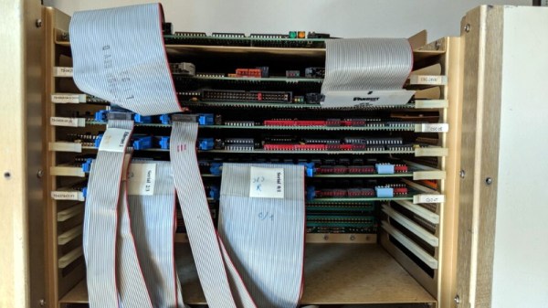
Cisco’s first commercial router, the Advanced Gateway Server (AGS), was released in 1986 and helped put the company (and the Internet) on the path towards unfathomable success. [Andreas Semmelmann] had wanted to add one of these microwave-sized machines to his collection for some time, so when an AGS+ popped up in the local classifieds he didn’t hesitate to make the hour drive to go pick it up. But like many pieces of vintage computing equipment, it needed a little help getting back on its feet.
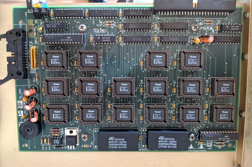
What 4 MB of flash looked like in the late 1980s.
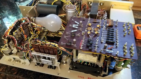
Since he had to take the router apart anyway to diagnose what ailed it, [Andreas] decided to take photographs along the way and document this piece of Internet history. He walks the reader through the massive processor, Ethernet, and serial cards that are housed in the unit’s rack-like enclosure. We appreciate him taking the scenic route, as it gives us a great look inside what would have been state-of-the-art telecommunications gear when this version of the AGS hit the market in 1989.
The walk-through is full of interesting details that make us appreciate just how far things have come in the last 32 years. Imagine yanking the EPROMs out of the board and firing up the UV eraser each time you needed to update your router’s firmware. Or needing a special adapter to convert the AUI-15 connectors on the back panel to the now ubiquitous RJ45 jack.
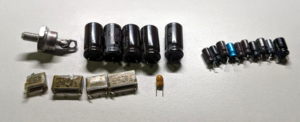
After this stroll down memory lane, [Andreas] gets to the actual repair work. It likely won’t surprise the regular Hackaday reader to find that the power supply wasn’t operating to spec, and that some aged capacitors and a shorted rectifier diode needed to be replaced to put it back on an even keel. But even with the PSU repaired, the router failed to start. The console output indicated the software was crashing, but hardware diagnostics showed no obvious faults.
Replacing these failed PSU components was just the beginning.
With some part swapping, firmware flashing, and even a bit of assistance from Cisco luminary [Phillip Remaker], the issue was eventually identified as a faulty environmental monitoring (ENVM) card installed in the AGS+. As luck would have it the ENVM capability isn’t required to boot the router, so [Andreas] was able to just disconnect the card and continue on with his exploration of the hardware that helped build the Internet as we know it.
It can be difficult for modern eyes to make much sense of electronics from the 1960s or earlier. Between the point-to-point soldering, oddball components, and the familiar looking passives blown up to comical proportions like rejected props from “Honey, I Shrunk the Kids”, even experienced hardware hackers may find themselves struggling to understand what a circuit is doing. But that didn’t stop [Cat0Charmer] from taking the time to lovingly restore this Hickok Cardmatic KS-15874-L2 tube tester.
The good news was that the machine had nearly all of its original parts, down to the Hickok branded tubes in the power supply. Unfortunately it looks like a few heavy handed repairs were attempted over the years, with a nest of new wires and components intermixed with what [Cat0Charmer] actually wanted to keep. The before and after shots of individual sections of the machine are particularly enlightening, though again, don’t feel to bad if you still can’t make heads or tails of the cleaned up version.
Hiding new capacitors inside of the old ones.
As you’d expect for a machine of this age, many of the original components were way out of spec. Naturally the capacitors were shot, but even the carbon composition resistors were worthless after all these years; with some measuring 60% away from their original tolerances.
We particularly liked how [Cat0Charmer] hollowed out the old capacitors and installed the new modern ones inside of them, preserving the tester’s vintage look. This trick wasn’t always feasible, but where it was applied, it definitely looks better than seeing a modern capacitor adrift in a sea of 60’s hardware.
After undoing ham-fisted repairs, replacing the dud components, and installing some new old stock tubes, the tester sprung to life with renewed vigor. The previously inoperable internal neon lamps, used by the tester’s voltage regulation system, shone brightly thanks to all the ancillary repairs and changes that went on around them. With a DIY calibration cell built from the schematics in an old Navy manual, [Cat0Charmer] got the tester dialed in and ready for the next phase of its long and storied career.
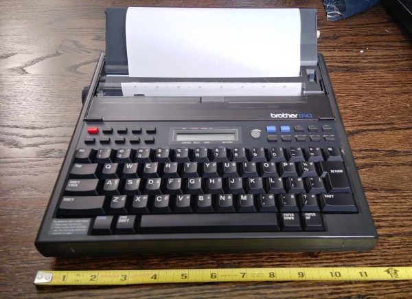
A few months ago, I fell down the internet rabbit hole known as Ted Munk’s typewriter site. I don’t remember if I just saw this Brother EP43 typewriter for sale and searched for information about them, or went looking for one after reading about them. Either way, the result is the same — I gained a typewriter.
Now I’m not really a typewriter collector or anything, and this is my first word processor typewriter. When it arrived from Goodwill, I anxiously popped four ‘C’ cells in and hoped for the best. It made a print head noise, so that was a good sign. But almost immediately after that, there was a BANG! and then a puff of smoke wafted out from the innards. My tiny typewriter was toast. Continue reading “Clacker Hacker: Popping A Cap In A Brother EP43 Thermal Typewriter”→
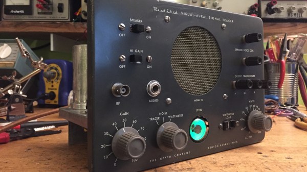
In its heyday, the experience offered by the Heath Company was second to none. Every step of the way, from picking something out of the Heathkit catalog to unpacking all the parts to final assembly and testing, putting together a Heathkit project was as good as it got.
Sadly, those days are gone, and the few remaining unbuilt kits are firmly in the unobtanium realm. But that doesn’t mean you can’t tear down and completely rebuild a Heathkit project to get a little taste of what the original experience was like. [Paul Carbone] chose a T-3 Visual-Aural signal tracer, a common enough piece that’s easy to find on eBay at a price mere mortals can afford. His unit was in pretty good shape, especially for something that was probably built in the early 1960s. [Paul] decided that instead of the usual recapping, he’d go all the way and replace every component with fresh ones. That proved easier said than done; things have changed a lot in five decades, and resistors are a lot smaller than they used to be. Finding hookup wire to match the original was also challenging, as was disemboweling some of the electrolytic cans so they could be recapped. The finished product is beautiful, though — even the Magic Eye tube works — and [Paul] reports that the noise level is so low he wasn’t sure if turned it on at first.