For years the proprietary spline pattern of rc servos has been a dealbreaker for hobbyists who want to add custom shafts and gears to their servos. First, different servo sizes have different spline sizes, and each vendor equips their servos with different patterns. True, some special vendors sell custom gears that mate to these patterns, but, overall, the hard-to-replicate pattern has severely limited the output options for servos.
This pattern didn’t deter [JB], however. With some clever CAD skills, and two working implementations, he’s demonstrated that these spline patterns can be (1) harvested and (2) added into custom components, opening a new suite of design opportunities involving servos.
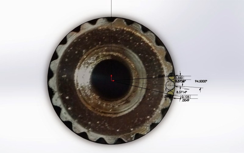
To capture the spline, [JB] imports an image into Solidworks, and traces the pattern on a properly scaled image. From there, he can embed this pattern directly into a physical model for fabrication.
To make parts that preserve this pattern, [JB] has two options. With his FormLabs printer, he can print components that already have the pattern feature, allowing him to press-fit custom links directly onto servos. Alternatively, for a sturdier component, he presents the milling method. With this technique, he drills a circle of bolt holes onto the desired output shaft and then mills out the center. From here, the shaft can also be directly pressed onto the servo spline where each spline groove fits snugly into the edge of the previously-drilled holes.
So, how well do they work? According to [JB] he’s actually managed to do some damage to himself before damaging to the 3D-printed part while trying to strip the pattern. The end-goal is to insert these shafts into transmissions for a miniature combat robot, another one of [JB’s] projects which is well-underway. Until then, we’re looking forward to seeing more servos tightly-integrated into upcoming projects.


I tried to do this and my part came out wrong! I used a flatbed scanner to generate my image, I can’t wait to read his methods
Servo output shafts
23 tooth spline – Sanwa / Airtronics / KO / JR
24 tooth spline – Hitec
25 tooth spline – Futaba / TT / ACE / HPI
+
Spline (teeth (gear Mesh) on Servo’s output shaft)
==================
23 teeth on the spline
-Sanwa
-Airtronics
-KO Propo
-JR Propo
-Graupner
-Multiplex
-Volz
-Cox
==================
24 teeth on the spline
-Hitec
-Hobbico
-Tower (System 2000)
==================
25 teeth on the spline
-Futaba
-Keil
-FMA
-Cirrus
-Vortex
-Duratrax
-HPI
-Tamiya
-Tower (System 3000)
-Traxxas
-Orion
The only other kind which you’ll ever encounter is a square 4mm thing, found on ancient radio gear like MRC
What about the diameters? I suspect they’re all different, which means there’s no “universal” 25-tooth spline pattern.
I can’t speak for all of the brands, but I can say that the 25 tooth shape servo horns fit well on several of the brands listed there. I suspect the situation isn’t as dire as one’s imagination could lead them to believe.
Its really the sort of thing which would be better broached rather than milled.
Less people have the knowledge to set it up but it gives a better finish and better local microstructure.
Do comercially available servo-spline broaches even exist? Even if they do, the number you’d need to fit the wide range of splines out there would make a set astronomically expensive for the use they’d get.
That said, as a communal or small-business workshop tool set, it could be very handy.
I used to work with a guy who had a custom broach made so that he could make his own control horns for servos. I didn’t ask how much it had cost but I bet it wasn’t cheap. He usually did animatronics work so it made sense for him to do this.
Third option: Pick spline gear, heat, press fit/melt on the piece with a base hole with a press (so it remains vertical and so on) There you go.
The lazy way is to just put some teflon tape or vaseline on the servo shaft, some epoxy in a gear hole and let the epoxy copy the form.
Smart, not lazy!!. Don’t need a 3D printer or a computer either :)
This. JB Weld works wonderfully without a lot of flex, though you have to be careful that it gets packed in really well. The metal version would be amazingly sturdy, but the printed one I’d worry about layer separation in torsion if it wasn’t done just right.
Is layer separation an issue on liquid resin printers?
one really simple, quick and dirty way to do metal casting in reasonable low temperature alloys is…
cuttlefish “bone” things.
sand down a smooth surface, then firmly push your thing into it, use 2 if you want to make a dual part mold and some sprue holes.
copper/tin alloys work well, as will lead alloys, I’ve not tried aluminium though.
I have seen my silver smith mate use them for silver and gold alloys.
I’ve done keys, miniatures, thumbscrews, small stuff like that.
you’ll be amazed at how much heat the “bone” thing can take!
Nice! I’ve lasercut suitable patterns before (after breaking the original servo arms) but those just had basic triangular teeth. They seemed to work well enough, but I’m sure that actually having the right profile would have made for a better fit with less slop.
It’s a testament to the resolution of his FormLabs printer that he can actually print that pattern; the Stratasys one I’ve used wouldn’t have a chance at that scale.
Nice hack, I especially like the way he acquired the fiddly bits from the photo, lots of potential for this technique! Also props for the awesome aluminium guitar he made.
Nice, but I don’t really see the difficulty here…
It’s a gear made from two circles and two lines, following the basic gear-mathematics.
I implemented a nifty little Solidworks table to generate a set of perfect-fit gears the other day using this page: http://makezine.com/2010/06/28/make-your-own-gears/
The same rules should apply for the servogears or am I missing something here?
Splines are not gears and often have very different contours, look at automotive transmission splines for instance. Splines are designed to transfer shaft power to a gear or other actuator on the shaft and although similar are not the same as gears.
OK, I see.
Still these splines here look even less complicated than gears.
It’s an obvious approach and to be frank: I usually expect more from a Hackaday posting.
I think someone who has legal access to solid works, a multi thousand dollars cad suite should not be praised too much for reverse engineering a mechanical part… That is most likely part of his day job.
I wonder if he asked the vendor for cad data. I am pretty sure you get anything you need. I mean these guys make a living of people interfacing things with their servos.
Do not be afraid hobbyists, there are professionals capable of reverse engineering splines! really? who would have thought that.
Yea screw that guy, he’s doing something semi-related to his job and sharing his useful findings with the community, what a jerk! He’s so entitled because his company lets him use a piece of software they own. I can’t possibly learn any valuable lessons from this, pull this article immediately.
In all seriousness listen to yourself.
You alternatively can simply use a pair of grub screws…not a problem at all in the torque ranges where this is encountered!
FormOne and most affordable resins uses an acryliate, making it brittle. MadeSolid’s Vorex claims to be very strong, but I don’t know how strong. The epoxy casting mentioned above might be an option. If you want to do metal, resin printing a castable material and cast it in metal. Or hiring it cut using wire EDM. But EDM is very expensive.
A broach would be helpful if you had to produce a lot of them.
The spline on a servo horn doesn’t go all the way through. Can you still broach a blind hole?
I’m imagining that a broach will produce a tapered hole, then a washer or screw with integrated washer will apply the holding force. Even if the hole is not tapered the servo shaft is likely shouldered.
Make a mold of the end of the shaft, or just integrate a shaft from a dead servo into the mold, and cast your servo attachment design in high strength urethane resin. You can even lay in some glass or carbon fiber cloth for extra strength.