Chilling A Hot Camera

[Eric]’s camera has a problem. It overheats. While this wouldn’t be an issue if [Eric] was taking one picture at a time, this camera also has a video mode, which is supposed to take several pictures in a row, one right after the other. While a camera that overheats when it’s used is probably evidence of poor thermal engineering, the solution is extremely simple: strap a gigantic heat sink to the back. That’s exactly what [Eric] did, and the finished product looks great.

The heatsink chosen for this application is a gigantic cube of aluminum, most likely taken from an old Pentium 4 CPU cooler. Of course, there’s almost no way [Eric] would have found a sufficiently large heat sink that would precisely fit the back of his camera, which meant he had to mill down the sides of this gigantic heat sink. [Eric] actually did this in his drill press using a cross slide vice and an endmill. This is surely not the correct, sane, or safe way of doing things, but we’ll let the peanut gallery weigh in on that below.

The heatsink is held on by a technique we don’t see much around here — wire bending. [Eric] used 0.055″ (1.3 mm) piano wire, and carefully bent it to wrap around both the heatsink and the camera body. Does the heatsink cool the camera? Yes, and the little flip-up screen of the camera makes this camera a very convenient video recording device. You can check out the video of this build below.

Continue reading “Chilling A Hot Camera”

An Electric Fence For Snails And Slugs

Anyone with a garden knows about doing battle with pests. Weeds, bugs, rabbits, birds — all of them try to get a bite out of our flowers and vegetables. Some of the worst are mollusks. Snails and slugs are notorious plant attackers. Tomato plants don’t stand a chance when these beasts come to town. Some folks would reach for the pesticide or even the salt, but [wheldot] had a better idea. He built an electric fence to keep these pests at bay.

Much like the electric fences used for large mammals like horses or cows, this fence is designed to deter, but not kill slugs and snails. The design is incredibly simple – two bare wires are strung around the raised garden about one centimeter apart. The wires are connected to a nine-volt battery. No boost circuit, no transistors, just nine volts across two wires. That’s all it takes to turn a slug away.

[Wheldot] didn’t come up with this hack — it’s been around in various forms for years. The nine-volt battery provides just enough current to annoy the slug or snail. The best part is that when not actively shocking a slug, the only current passing through the circuit is the whatever is passed through the wood.

Reddit user [gnichol1986] measured that at around 180 kΩ through wet wood. That means a typical 400 mAh battery would last around 34 days of continuous rain. Even in the UK it doesn’t rain that much. With a little work insulating the wires from the wood, that could be extended to the full shelf life of the battery.

You know, slugs and critters get into electronics too, so don’t forget a waterproof case to make sure your project stays slug free!

Continue reading “An Electric Fence For Snails And Slugs”

Key To Soldering: Pace Yourself

When writing my last article, I came upon something I thought had been lost to the seven seas of YouTube: the old-school “Basic Soldering Lesson” series from Pace Worldwide.

This nine-episode-long series is what retaught me to solder, and is a masterpiece, both in content and execution. With an episode titled “Integrated Circuits: T0-5 Type Packages & Other Multi-leaded Components” and a 20-minute video that only focuses on solder and flux, it’s clear from the get-go that these videos mean business. Add that to the fact that the videos are narrated by [Paul Anthony], the local weatherman in the Washington DC area back in the 80s and 90s, these videos are a joy to watch.

Even if you know what you’re doing, don’t skip the first video. It’s where the “workpiece indicator” concept, which runs throughout the series, is introduced.

Covering everything from what solder really is to how to correctly solder integrated circuits, this series has it all, even if it’s slightly dated. And, while it’s not a hack, it’s a great way to rejuvenate your soldering skills or give someone a hot start on their soldering journey.

Speaking of which, we’ve seen many things designed to educate, but one size certainly does not fit all. Do y’all know of any well-made sources that teach foundational topics that are as accessible as this series? If so, let us know in the comments.

The first video in the series is after the break. In sum, they’re long but worth it.

Continue reading “Key To Soldering: Pace Yourself”

Three Magnets Make Fidget Spinners Amazing And Only Engineers Will Appreciate This Hack!

The fidget spinner posts will continue until morale improves. This time, we’re looking at [TannerTech]’s electromagnetic accelerator for a fidget spinner. [Tanner] can spin his fidget spinner electronically using parts he had sitting around and a clever application of magnets and relays! Engineers hate him!

[Tanner]’s build consists of three magnets mounted on the tip of a fidget spinner’s arms, with the North pole facing outwards. The ‘drive circuit’ consists of an electromagnet — an inductor [Tanner] found in an old TV set — a reed switch, and a MOSFET. When the circuit is placed next to the fidget spinner, the reed switch closes, powering the electromagnet, pushing the tip of the fidget spinner forward, and starting the cycle anew. Think of it as the same technology that goes into a particle accelerator or a maglev train. Or a brushless DC motor.

Haven’t gotten your daily fill of fidget spinner hacks and fidget spinner news? Don’t worry, because we got your back, fam. Check out this amazing way to teach STEAM education — the ‘A’ stands for ‘arts’ — with the help of fidget spinner shaped PCBs and a flanged bearing. Is your oscilloscope too boring? Spice it up with some fidget spinner awesomeness. Useless machines are cool, and even [Marvin Minsky], the father of Artificial Intelligence, would say this fidget spinner hack is amazing. Like, share, and subscribe for the latest in fidget spinner news.

It’s great, if slightly ironic, to see people doing something other than fidgeting with their fidget spinners. Who would have thought a fad that began as a few extra skateboard bearings and a 3D-printed blob of plastic would beget so many truly interesting hacks? You can check out [Tanner]’s build video of this amazing hack below.

Continue reading “Three Magnets Make Fidget Spinners Amazing And Only Engineers Will Appreciate This Hack!”

Braille keypad circuit board

Hackaday Prize Entry: A Braille Keypad For SmartPhone

A few things stand out about [Vijay]’s braille keypad for smartphones. One is how ergonomic the plans for the final result are, sitting on the back of the smartphone such that you hold the phone much as you often normally would. Another is that it plugs in just like any other USB keyboard. And the last should make any vi user smile — you don’t have to move your fingers to type. You just press combinations of buttons already under your fingers.

It consists of a custom circuit board with an AtMega32U4, a 16 MHz oscillator, a Micro-USB connector and eight pushbutton switches.  The AtMega32U4 allows him to use the Arduino HID library. After mapping the braille button combinations to keys, the HID library sends the key values over a USB-OTG cable to the smartphone to be accepted as if they were coming from a normal plug and play keyboard.

We have to give kudos to [Vishay] for testing with blind people experienced with braille. For example, he’s learned that if the user presses [Dots 1 2] for ‘b’ followed by [Dots 1 4] for ‘c’, they prefer to not have to remove their finger from the 1 in between the two characters, for more rapid typing.  He also learned that battery management is problematic and that may be why he’s since abandoned the option of communicating over Bluetooth, leaving just USB, and thereby eliminating the need for a battery.

[Vijay]’s project is a finalist for the Internet of Useful Things Hackaday Prize and we’re eager to see what the final result will look like. But in the meantime, check out his hackaday.io and GitHub pages, and see the video below of one iteration of his keypad in use.

Continue reading “Hackaday Prize Entry: A Braille Keypad For SmartPhone”

Making Spirographs With LEGO And Math

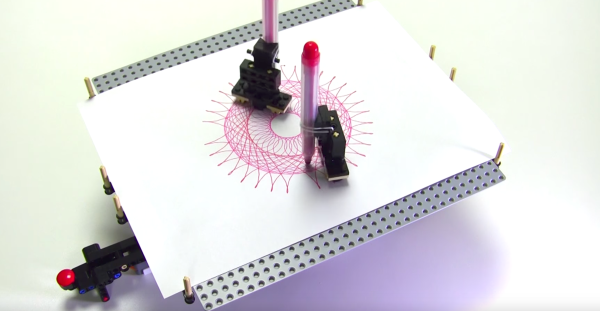
Master LEGO builder [Yoshihito Isogawa] has been on a roll lately, cranking out a number of robots that make drawings reminiscent of the classic Spirograph toy. For instance, he built an elegant drawbot out of LEGO elements, seen above. At first glance the monicker “spirograph” seems wrong, because where are the gears? However, [Yoshihito] has them stashed underneath the sheet of paper, with magnets controlling the pens.

His drawbot consists of a platform (cleverly, an inverted LEGO plate) upon which a sheet of paper is laid. One or two pen holders, each with a pair of magnets underneath, rest on the sheet of paper. Beneath the plate, two pairs of spinning magnets rotate around a double layer of 11×11 curved racks, which then play the role of the classic spirograph rings. An EV3-controlled motor powers the whole thing.

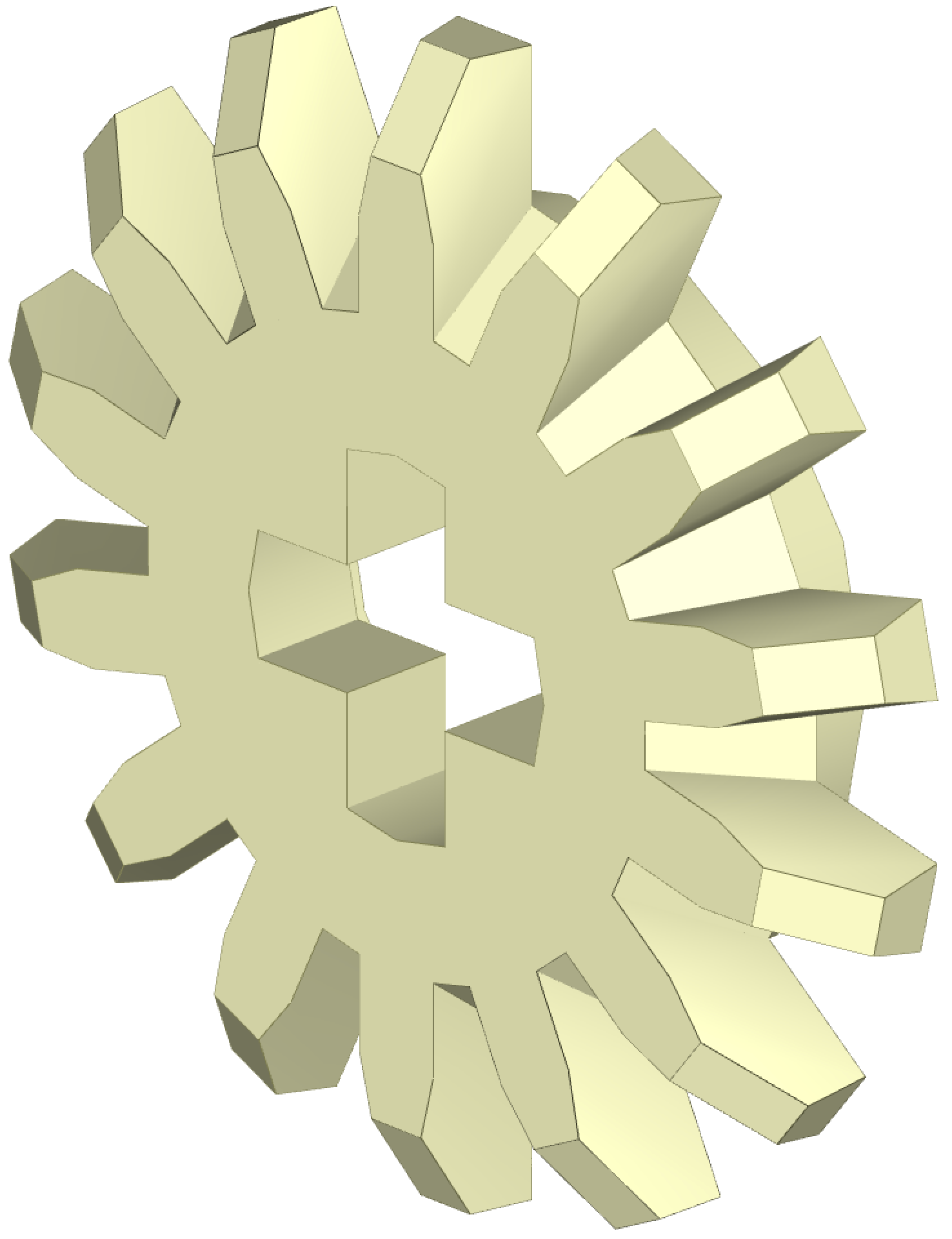
He also makes use of an obscure part–the 14-tooth bevel gear, last manufactured by LEGO in 2002 and even then it was mostly sold in part assortments intended for the education market. It’s so obscure LEGO doesn’t even provide the gear in their online building program LEGO Digital Designer, though (of course) the LDraw folks re-created it — it’s brick 4143 in the library, seen below.

Spirograph Gear Math

This gear becomes important in spirograph-style projects because tooth count is everything. There really aren’t that many spirograph designs that can be made with LEGO, because there are a limited number of gears and they mostly have the same tooth counts–the smaller ones sport 8, 12, or 16 teeth, medium-sized ones 20 or 24 teeth, and larger ones 36 or 40 — see a pattern? Such predictability may be great for a building set, but it doesn’t engender a lot of spirograph diversity.

When you compute the number of vertices in a spirograph shape, you take the least common multiple of the two gears (or sets of gears) and divide by the small gear. So a 60-tooth turntable turning a pair of 14-tooth gears has an LCM of 420, and you divide by 28 to get the number of vertices: 15. Remove one of those smaller gears and the vertices increase to 30. The challenge in creating new shapes with a LEGO spirograph lays in swapping in new gears, just like the original toy, and having more ways to come up with unusual gear ratios makes for more interesting drawings.

Another that makes the 14-tooth gear so alluring to [Yoshihito] is that it’s one of the few LEGO gears with a number of teeth not divisible by 4. Among other things this means the gear meshes with an identical gear at 90 degrees. Usually the gears have the same number for each quarter of the circumference and meshing becomes a matter of jogging one gear a scosh. This can be a problem because LEGO axles have a “plus” shaped profile, and you may not want everything on that axle tilted as well — having a 90-degree solution makes a lot of sense.

[Yoshihito] designs LEGO robots out of Isogawa Studio and has written several books on advanced LEGO techniques, published by No Starch. He specializes in small and elegant mechanisms — finding the perfect set of elements that work together effortlessly. You can see an example in the gear assembly to the right — a pair of the aforementioned 14-tooth bevel gears, turned into a normal gear with the help of that golden spacer, none other than a One Ring from LEGO’s Lord of the Rings product line. You can find videos of his projects on YouTube.

[Yoshihito] has released a number of variants of the spirographing drawbot. What’s next? Maybe a harmonograph?

Continue reading “Making Spirographs With LEGO And Math”

An ExoArm For The Elderly

Prosthetic and assistive technologies have come have come a long way in recent years. When there are not only major medical research organizations, but individuals getting on board designing tools to improve the lives of others? That’s something special. Enter a homebrew essay into this field: ExoArm.

Attached to the body via what was available — in this case, the support harness for a gas-powered weed-eater — which distributes the load across the upper body and an Arduino for a brain, ExoArm designer [Kristjan Berce] has since faced roadblocks with muscle sensors meant to enable more instinctive control. So — for now — functionality is limited to a simple up and down motion controlled by two switches. It is worth noting that the down switch is currently mounted in such a way that when the user moves their arm down, the ExoArm follows suit, so there is some natural feel to using the arm in its present iteration.

Continue reading “An ExoArm For The Elderly”