Better VGA On The STM32F4

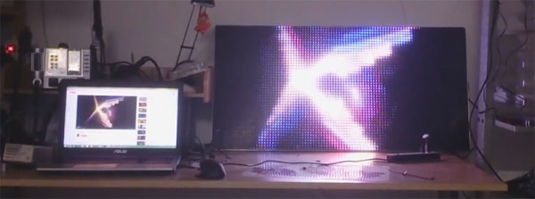
[Cliff] is pushing VGA video out of a microcontroller at 800×600 resolution and 60 frames per second. This microcontroller has no video hardware. Before we get to the technical overview, here’s the very impressive demo.

The microcontroller in question is the STM32F4, a fairly powerful ARM that we’ve seen a lot of use in some pretty interesting applications. We’ve seen 800×600 VGA on the STM32F4 before, with a circles and text demo and the Bitbox console. [Cliff]’s build is much more capable, though; he’s running 800×600 @ 60FPS with an underclocked CPU and most (90%) of the microcontroller’s resources free.

This isn’t just a demo, though; [Cliff] is writing up a complete tutorial for generating VGA on this chip. It begins with an introduction to pushing pixels, and soon he’ll have a walkthrough on timing and his rasterization framework.

Just because [Cliff] has gone through the trouble of putting together these tutorials doesn’t mean you can’t pull out an STM Discovery board and make your own microcontroller video hacks. [Cliff] has an entire library of for graphics to allow others to build snazzy video apps.

Swapping Dev Board Crystals To Suit Your Needs

Microcontroller Dev Boards have the main hardware choices already made for you so you can jump right into the prototyping by adding peripherals and writing code. Some of the time they have everything you need, other times you can find your own workarounds, but did you ever try just swapping out components to suit? [Andy Brown] documented his process of transplanting the clock crystal on an STM32F4 Discovery board.

Even if you don’t need to do this for yourself, the rework process he documented in the clip after the break is fun to watch. He starts by cleaning the through-hole joints of the crystal oscillator with isopropyl alcohol and then applies some flux paste to each. From there the rest is all hot air. The crystal nearly falls out due to gravity but at the end he needs to pluck it out with his fingers. We’re happy to see others using this “method” as we always feel like it’s a kludge when we do it. Next he grabs the load caps with a pair of tweezers after the briefest of time under the heat.

We’d like to have a little bit of insight on the parts he replaces and we’re hoping there are a few crystal oscillator experts who can leave a comment below. [Andy] calculates a pair of 30pf load caps for this crystal. We understand the math but he mentions a common value for board and uC input capacitance:

assuming the commonly quoted CP + CI = 6pF

So we asked and [Andy] was kind enough to share his background on the topic:

It’s a general “rule of thumb” for FR4 that the stray capacitance due to the traces on the board and the input (lead) capacitance of the the MCU is in in the range of 4-8pF. I’m used to quoting the two separately (CP,CI) but if you look around you’ll see that most people will combine the two and call it just “CP” and quote a value somewhere between 4 and 8pF. It’s all very “finger in the air” and for general purpose MCU clocks you can get away picking the mid-value and be done with it.

That leaves just one other question; the original discovery board had an in-line resistor on one of the crystal traces which he replaces with a zero ohm jumper. Is it common to include a resistor and what is the purpose for it?

Continue reading “Swapping Dev Board Crystals To Suit Your Needs”

RGB LED Matrices With The STM32 And DMA

A few years ago, [Frans-Willem] bought a few RGB LED panels. Ten 32×16 panels is a lot of LEDs, and to drive all of these panels requires some sufficiently powerful hardware. He tried working with an FPGA development board, but that didn’t have enough memory for 24-bit color. The microcontroller du jour – a TI Stellaris – couldn’t get more than 16 bits of color without flickering. With a bunch of LEDs but no way to drive them, [Frans-Willem] put the panels in a box somewhere, waiting for the day they could be used to their fullest capacity.

This day came when [Frans-Willem] was introduced to the STM32 series of chips with the F1 Discovery board. While looking for some electronic playthings to use with this board, he stumbled upon the LED panels and gave them one more try. The results are spectacular, with 33 bits of color, with animations streamed over a router over WiFi.

The panels in question are HUB75 LED panels. In the 32×8 panels, there are six data pins – two each for each color – four row select pins, and three control pins. The row select pins select which row of pixels is active at any one time. Cycle through them fast enough, and it will seem like they’re all on at once. The control pins work pretty much like the control pins of a shift register, with the data pins filling in the obvious role.

The code that actually drives the LEDs all happens on an STM32F4 with the help of DMA and FSMC, or the Flexible Static Memory Controller found on the chip. This peripheral takes care of the control lines found in memory, so when you toggle the write strobe the chip will dump whatever is on the data lines to a specific address in memory. It’s a great way to take care of generating a clock signal.

For sending pixels to this display driver, [Frans-Willem] is using the ever-popular TP-Link WR703N. He had originally planned to send all the pixel data over the USB port, but there was too much overhead, a USB 1.1 isn’t fast enough. That was fixed by using the UART on the router with a new driver and a recompiled version of OpenWRT.

All the software to replicate this project is available on Github, and there’s a great video showing what the completed project can do. You can check that out below.

Continue reading “RGB LED Matrices With The STM32 And DMA”

800 X 600 VGA With The STM32F4

Generating VGA is a perennial favorite on the Hackaday tips line, and it’s not hard to see why. Low-res video games, of course, but sending all those pixels out to a screen is actually a pretty challenging feat of coding. The best most project have attained is the original VGA standard, 640×480. Now that we have fast ARMs sitting around, we can bump that up to 800×600, like [Karl] did with an STM32F4 Discovery board.

The problem with generating VGA on a microcontroller is the pixel frequency – the speed at which pixels are shoved out of the microcontroller and onto the screen. For an 800×600 display, that’s 36 MHz; faster than what the 8-bit micros can do, but a piece of cake for the STM32F4 [Karl] is using.

[Karl] started his build by looking at the VGA project Artekit put together. It too uses an STM32, but a 36-pin F103 part. Still, it was fast enough to generate a line-doubled 800×600 display. [Karl] took this code and ported it over to the F4 part on the Discovery board that has enough space for a full 800×600 frame buffer.

With all that RAM on board the F4 part, [Karl] was able to expand the frame buffer and create a relatively high-resolution display with DMA and about a dozen lines of code. It looks great, and now we just need a proper application for high-resolution VGA displays. Retrocomputing? A high-resolution terminal emulator? Who knows, but it’s a great use for the STM32.

If circles and some text aren’t your thing, Artekit also has Space Invaders running on the 36-pin STM32.

Espruino Pico, Javascript On A USB Stick

There are probably very few official numbers for this, but web developers at least seem to outnumber the amount of people who regularly poke pins and registers with C. For them, the embedded world must be a scary and foreboding domain, full of bitwise operations and dynamic types. [Gordon] figured there was another way and built a Javascript interpreter for a microcontroller. The latest board built around this interpreter is up on Kickstarter, and its even smaller and more capable than his earlier version.

This isn’t [Gordon]’s first rodeo; last year he launched the (full-sized) Espruino, featuring an ARM Cortex M3 and his very own Javascript interpreter. The large-scale Espruino was a rousing success, and now he’s moving on to a smaller thumb drive-sized footprint for the Pico. The hardware is a bit better, relying on the ARM Cortex M4 STM32F4 with a bit more RAM, and this time the board is slightly cheaper. It still runs the same Javascript interpreter, though, so all the code is exactly what you’d expect.

We haven’t seen many projects using this tiny Javascript of Things, but the new layout does make it fantastically useful. Depending on how the crowd funding campaign turns out, [Gordon] might be adding socket, and USB HID support, along with inline C functions.

A Complete C64 System, Emulated On An STM32

The Commodore 64 is the worlds bestselling computer, and we’re pretty sure most programmers and engineers above a certain age owe at least some of their career to this brown/beige keyboard that’s also a computer. These engineers are all grown up now, and it’s about time for a few remakes. [Jeri Ellisworth] owes her success to her version, there are innumerable pieces of the C64 circuit floating around for various microcontrollers, and now [Mathias] has emulated everything (except the SID, that’s still black magic) in a single ARM microcontroller.

On the project page, [Mathais] goes over the capabilities of his board. It uses the STM32F4, overclocked to 235 MHz. There’s a display controller for a 7″ 800×480 TFT, and 4GB of memory for a library of C64 games. Without the display, the entire project is just a bit bigger than a business card. With the display, it’s effectively a C64 tablet, keyboard not included.

This is a direct emulation of the C64, down to individual opcodes in the 6510 CPU of the original. Everything in the original system is emulated, from the VIC, CIAs and VIAs, serial ports, and even the CPU of the 1541 disk drive. The only thing not emulated is the SID chip. That cherished chip sits on a ZIF socket for the amazement of onlookers.

You can check out some images of the build here, or the video demo below.

Continue reading “A Complete C64 System, Emulated On An STM32”

A Cloud Of Lightning Detectors

strikes

Here’s an interesting project to plot every lightning strike on Earth. Blitzortung is a project that uses many extremely low-cost sensor boards packed with an amplifier, microcontroller, and an Ethernet socket to detect lightning strikes. When multiple stations send all that data up to a server, the location of lightning strikes can be calculated, even if they’re hundreds of miles away from any station.

Each station works by detecting a change in the local EM field caused by a lightning strike with either a large loop antenna or a smaller ferrite core antenna. These signals can be amplified and turned into usable data, time stamped, and sent out on the Internet. From there, it’s a simple time of flight calculation to precisely locate where lightning strikes.

The hardware is actually pretty simple, with based on an STM32F4 Discovery board. A controller includes an Ethernet port, GPS unit, LCD, and all the hardware associated with detecting lightning strikes.

If you’d like to see what’s possible with a huge network of lightning detectors connected to the Internet you can check out LightningMaps for a look at what’s possible.

Thanks [Sean] for sending this in.