Sumo Style Robot

[Jeremy] really wants to compete in some sumo bot wrestling, and in order to have robotic sumo wrestling one needs to make some robots, which is what [Jeremy’s] build log is all about.

The framework is made out of 6mm thick Sintra (which is a type of closed cell pvc foam sheet) with the use of a CNC machine, using a “sliced” design style framework. Two geared motors fit snug inside of the internal frame and some wheels from solarbotics are attached to the ends. The arrangement of the drive wheels in the rear, and the large front end, seems like good design for the end application where robots doing turtle flips would be no fun.

Keeping in mind this is not a fully finished project and therefore does not have code or schematics posted, the brains of this beast are in a similar state, and should be pretty easy to figure out. The thinking is handled by an atmega328, and fed by IR sensor pair’s to detect light / dark patterns on the floor or table, and an array of proximity sensors along the front and sides to detect its opponent.

And while this project may not be completed, it at one point was dead and set aside, after some months [Jeremy] went back for a second look and found out that the only thing dead about it was the power regulator and h-bridge and quickly got it back up and working, which is a good reminder to not give up, even when it does go poof.

Update To Stairmonster

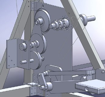
The “Stairmonster 2” is an updated verison of the hyper speed, home brew stairmaster we covered back in November. It still features most of its original version’s features including a very sturdy construction, heart rate monitor, and 320×240 touchscreen interface. What is new about the Stairmonster 2 is its handlebars. V1 used stationary bike handlebars, which would be good for pull-ups or other similar exercises, but did not do much good while on the machine.

Version 2 on the other hand uses moving handles, when paired with the resistance of the machine allows the user to simulate a climbing action. The handles are also attached to rotary slip clutches so there is only resistance on the pulling cycle and not while retracting, which could be very bad at the speed this thing can run at.

Overall a good improvement to an already impressive machine, though don’t expect to see us climbing on it anytime soon.

Pong Clocks Using LED Matrix Modules

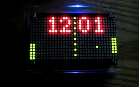
We love Pong clocks because they’re showpieces. This particular offering, called the Wise Clock, is the third hardware revision of the project. The LED display is dead simple since they’re using a 32×16 bi-color module from Sure Electronics. If you don’t want to design and build your own multiplexing display this is a somewhat inexpensive and high-performance alternative.

After the break you can see that the paddle movements look very realistic. They move like a human player might, which is quite often not the case with these clocks. If you want to see how that’s done, check out the code which was originally developed by [123led] for a different project.

Continue reading “Pong Clocks Using LED Matrix Modules”

Animating An LED Matrix Without A Microcontroller

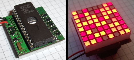
[Konstantin] had some extra 27C256 EPROMS lying around and decided to use them to animate an 8×8 LED matrix. He’s not only using them to store data, but driving the display with them as well. The chip holds 32 kilobytes of data which equates to 4096 frames of animation. A 32 kHz clock circuit works with some ripple counters to scroll through each byte of stored data, turning on the columns while sinking the proper row. Of course current protection is a must so there is a ULN2308A darlington driver and some 2N2907 transistors at work, but you won’t find a programmable microcontroller. Neat!

Yep, you read that right. The picture above shows an EPROM chip that requires a UV light source to erase the data.

[Thanks Kopfkopfkopfaffe]

Wireless Arduino Message Board

arduino_message_board

[uhclem] was looking for a novel yet easy way to remind his kids to do their chores, and instead of using a series of post-it notes, he constructed a nice wireless Arduino-powered message board.  The message board is powered by an Arduino Pro, and communicates with his computer via a pair of series 1 Xbee radios which relay a series of canned messages to an attached VFD.  He installed all of the components in an old cigar box, and mounted it on the wall, making for a nice overall presentation.

Programming of the messages does not require any special software as the user interface is handled by the Arduino and accessed via a standard terminal session. [uhclem] mentions that the his code consumes nearly all of the device’s RAM when running, so he keeps a handful of canned messages stored in the Arduino’s flash memory, recalling them when needed.  The optional EEPROM is used to allow for streaming messages to the device as well.

Grinding Down Your Computer To Just 8.5 Watts

What can you do to make sure your system is running as efficiently as possible? Take a page out of [Mux’s] book, who went to great lengths to measure and adjust his system for ultimate efficiency (translated). What he ended up with is 8.5 Watts of consumption at idle and about 50 Watts under load. Luckily he posted a six-part series with all of the details.

Some of the changes he made were in software, like reducing voltage to certain hardware by adjusting BIOS settings, and installing display drivers that put the screen into the proper sleep mode. Others were hardware changes like swapping out the power supply with a hacked PicoPSU and removing unnecessary parts from the motherboard like the MAX232 com-port chip. Looks like we need to audit our always-on MythTV box and see if we can apply any of these power-saving techniques.

[Thanks Gijs]

555 Timer Circuit Simulation Software

ltspiceiv_demo

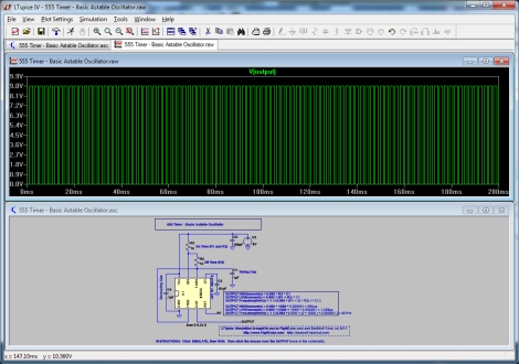
[FightCube] wrote in recommending a very helpful piece of circuit simulation software for those of you still constructing entries for the 555 design contest.   LTSpiceIV, available from Linear Technology, allows you to construct moderately complex 555 driven circuits including common components such as capacitors, resistors, diodes, FETs, and more.  Once you have constructed your circuit, you can view the results in an easy to use visualization window, without ever having to touch your soldering iron or a breadboard.  According to [FightCube], the software is fairly easy to use, and best of all, it’s free.

He has shared one basic circuit he built as a demonstration of the software’s capabilities, and promises to share more in order to motivate others to enter the contest.