Pong Clocks Using LED Matrix Modules

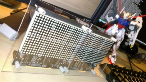
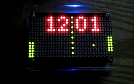
We love Pong clocks because they’re showpieces. This particular offering, called the Wise Clock, is the third hardware revision of the project. The LED display is dead simple since they’re using a 32×16 bi-color module from Sure Electronics. If you don’t want to design and build your own multiplexing display this is a somewhat inexpensive and high-performance alternative.

After the break you can see that the paddle movements look very realistic. They move like a human player might, which is quite often not the case with these clocks. If you want to see how that’s done, check out the code which was originally developed by [123led] for a different project.

Continue reading “Pong Clocks Using LED Matrix Modules”

Bluetooth Temperature Module

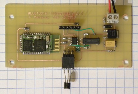
Wanting to know the outside temperature, [Jamie Maloway] built his own temperature sensor that can be read with a Bluetooth device. Let’s take a tour of the hardware above from right to left. There’s a linear voltage regulator with two filtering caps and a terminal block to attach a 9V battery or other power source. Next there’s an 8 MHz crystal and it’s capacitors, followed by a programming header on top and a 1-wire temperature IC, the DS18B20 we’re all familiar with hanging off the bottom. These both connect to the 8-pin PIC 12F675 that drives the system, and transmits using a Bluetooth module from Sure Electronics. Since this is using a serial protocol and transmitting ASCII data, it can be read using an automated script, or simply by using a terminal program.

Now, who’s going to be the first to get rid of the battery and leech off of the mains through inductance?

Communicating With An LED Matrix

Most of the LED matrix posts we run delve into the hardware design. This time around [J Bremnant] used prefab modules and focused on writing code to address the display. The hardware combines two 24×16 LED boards from Sure Electronics with a Teensy 2.0 to drive the display and provide a USB connection. The firmware comes in just under 8k, leaving graphic manipulation up to a PC.

[J Bremnant’s] Python script offers a lot of flexibility when working with the display. There are three modes selectable through a terminal interface. One just tests the display and then drops into Conway’s Game of Life. The second mode lets you send commands via serial interface so it can be used as a message ticker. The final feature is frame addressing that allows graphics to be dropped into the display. See each of these featured in the video after the break.

Continue reading “Communicating With An LED Matrix”

LEDs Invade Coffee Table Crevice

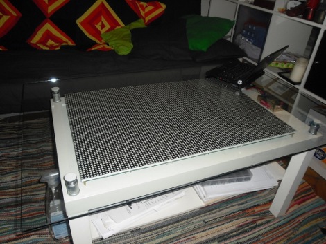
That’s a lot of LEDs, and a little bit of glass cleaner. [Tobias] spiced up his IKEA coffee table by adding 6144 LEDs. This is a larger realization of SparkFun’s LED coffee table which used 64 8×8 modules. [Tobias] sourced three display boards from Sure Electronics for a total of 96 8×8 modules. These boards are addressed through a serial interface; four serial lines for each board but a shared data bus for each of the row select pins and the data/latch/clock pins.  This method uses 19 of the 20 pins on the Arduino that drives the display. After the break you can see a demonstration. If this is more than you need there’s always the 112-LED and 81-LED table projects that can produce a full color range. Continue reading “LEDs Invade Coffee Table Crevice”