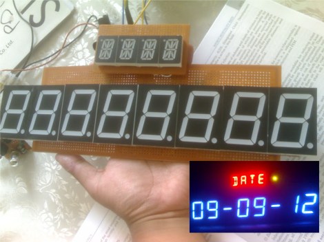
One look at this display and you know there’s a whole lot of pins that need to be wired up. Now look at what those display modules are mounted on. That’s right, [Kemley] is using point-to-point soldering to rig up this big display. It sports four sixteen segment modules on top for alpha-numeric information, and eight large seven segment modules for displaying numbers only.
We’re not certain as to how the electronics are arranged. When talking about the 16-segment modules he mentions that all four are in parallel with NPN transistors to switch the common anode of each. That’s easy enough to understand. But when you get a look at the transistor board you’ll see 24 of them in use. He’s included a 150 ohm resistor on the collector of each transistor. It must be set up to only allow one segment of each group to switch on at a time? We’d guess that each segment is divided into two (upper and lower pins are multiplexed separately), which would explain the double set of transistors. As for date and time, an Arduino board monitors a DS1307 RTC and manages the scanning of the display.


And this guy is a final year medical student. Makers…Makers everywhere!
Cool display – but would an IC array (ie. ULN2004) be a more compact choice for this project?
Given the size of the segments, it doesn’t strike me as something that’s high on his list of priorities.
The ULN2004 is a darlington array,with diode protection, so it’s great for driving motors, but the darlington pair has a diode drop, and on low voltage systems (5-3.3v) it can be significant loss, and if there is a space concern, the transistors can be arranged to take up less space than that IC.
Why are they called 16-segment displays when there are only 14 segments?
Zoom in on the picture: the top and bottom segments are split, these are 16 segment displays.
Check this appnote : http://www.maximintegrated.com/app-notes/index.mvp/id/1131
I see he’s using the traditional one-resistor-per-LED to limit current. Would it be possible (or worthwhile) to use a single digital variable resistor on the common line instead? If you continuously adjusted it to match the number of LEDs lit at any given time, presumably you could simplify the hardware design without any noticeable brightness changes as the display is operating. Or would this not work?
How about having a common resistor and lighting only one segment at a time? If you go fast enough, the flickering should be unnoticeable.
Has anyone tried that? Does it work?
Interesting thought. You would have to keep your “loop time” constant though, so that each segment flickers at the same rate no matter how many other segments are lit (otherwise one lit segment would be on 100% of the time, but two lit segments would each be on 50% of the time at half the brightness.) If you had 160 segments and each segment was on for 1/160th of the cycle even if it was the only segment lit, then there should be no brightness changes. But this would then mean your LED would only be 1/160th as bright as it normally is, so maybe it would be too dark to see?
I know multi-segment LED displays (like those for alarm clocks) reduce their pin count by having two or three common lines, with the rest of the pins illuminating different segments depending on which common line is connected at the time. These displays flicker imperceptibly (cycling between each common line), so that part would be fine, but in this case each LED is on for a third of the cycle, rather than (say) 1/160th.
So I guess the reason this isn’t done is because the resulting display would be too dim.
Or…..
You could just take advantage of the LED peak rating and forget the resistor entirely. More work on the timing but hey… consider it a good programming exercise.
When I did something like this I eliminated the resistors by providing the LED’s forward voltage exactly. If an LED is rated for say 2.4V and you supply exactly 2.4V you don’t need any current limiting.
that could be a method, but somehow you got to limit thee voltage to that point, and it’s completely unusable if you use different kinds of led-s.
also it depends on the fact that all the leds have the same characteristics and it’s not a really good designs if you ask me.
i don’t think that is better than a resistor per led group. (and resistors so cheap that they are almost free.)
@ malvineous
Most LED clocks reduce pin count even further by driving the display with alternating current. There is a specific IC made for this (i forget the part number).
first i say awesome looking display, its HUGE!
i think alarm clock led displays do that. the AC thing that is.
the top and bottom are multiplexed, but instead of two wires (one for each half), instead its one wire thats common anode for top of display and common cathode for the bottom… or the oppisite
plus the usual “one common for each digit”
so instead of 4 + 8 wires, its 4 + 4 wires and AC on the digit selects
why else do they all (1970-1990) seem to use center-tapped transformers? … center tapped is more expensive.
when using a center tapped transformer, the top leg (is rectified into) is + DC, the bottom leg (is rectified into) is – DC and the middle is AC @ half the voltage… for LED AC common(s)
looks like someone is building a certain mobile time machine. The real trick is generating the 1.2 Jiggawatts that make time travel possible
Next problem is finding someone that puts all that flux in a capacitor for you. :D