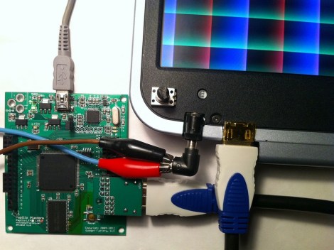
We love to see derivative works that take a great hack and make it even better. This LCD Laptop resurrection project is an excellent example. [Alex] took the work seen on this other FPGA LCD driver and delivered a leap forward on the final hardware packaging.
The link at the top drops you into the second page of [Alex’s] project thread. But if you go back to the beginning you’ll see the protoboard and spaghetti wiring which started off the process. Obviously if he plans to use this for a length of time it needs to be fortified or he’ll be cracking it open and grabbing a soldering iron again before long. But rather than just tidying up he ended up spinning his own circuit boards that make the screen look like it was manufactured to be used in this way.
He was able to mount the add-on board inside the LCD bezel, cutting out a space for the HDMI connector, barrel jack, trimpot, and the head of the inductor which was just a bit too large to fit inside. The trimpot allows him to adjust the LCD brightness. As far as we can tell the HDMI connector is just an easy way for him to deliver the drive signals from the Papilio board (FPGA) to the screen.


and the website is down from the load :D
His comments on the site say the trim-pot -would- have adjusted brightness, but it’s not connected to the right pins to do so.
Very nice hack. This site needs more of this stuff on hackaday.