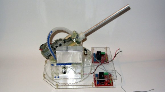
Yet another project that proves you need to acquire a laser cutter. This Airsoft turret rotates, tilts, and includes a hopper for ammo.
All of the pieces were cut from acrylic. The base includes a bracket which keeps the large rotating gear level by sandwiching it between the layers. That and the tilt mechanism are pretty straight forward. The module responsible for loading the BBs is pretty neat though. It uses a gear with round teeth the same diameter as the ammo. Once a BB is picked up it is forced upward into the tubing that feeds the gun. Get the full picture from the demo video after the break.
The one thing [The Liquider] is wondering about is how to provide feedback for the tilt and rotate functions. We can’t think of an easier way than to use simple rotary encoders. The Arduino Mega he wishes to use as a driver will have no problem interfacing with reflectance sensors and the acrylic makes it simple to mount this type of black and white encoder wheel.


Austrian systems makes a couple of magnetic encoders.
You spin a small magnet 1 or 2 mm above the IC and it senses the rotating magnetic field using some hall effect sensors and does processing on that to determine and output the angle in a couple of formats.
They’re 8,10, or 12 bits of resolution (depending on chip) and they have PWM, Analog, SPI, and quadrature versions.
here is one i picked at random. AS5132
Or, you could always go for a potentiometer or have a low-resolution quadrature encoder using some LEDs, photodiodes, and a perminent marker.
Maker bot sell these as a kit, but very expensive.
http://store.makerbot.com/magnetic-rotary-encoder.html
How ridiculously expensive. Mad Scientist Hut has the same thing for less than half the cost.
http://www.madscientisthut.com/Shopping/agora.cgi?cart_id=2148900.11262&product=CNC%20/%20Robotic%20Sensors&user4=Rotary%20Encoder&xm=on
that is an excellent idea! Thank you very much!
Paint your gears black at the tip and use the teeth as encoders…
Use some digital AX-12 servos.
Then mount on a quad and enter Mech Warfare, duh.
—-
Also, what hopup/barrel are you using? I’ve never been able to identify a hopup that would definitely work with those gearboxes (documentation on airsoft hardware-selling sites is pathetic).
Its a gearbox from a cheap G36 Airsoft, including the barrel! Theres a little hopup device which can be turned on an off.
Sticking black and white “pie chart” encoders on the body of the turret limits the resolution. I played around with this and couldn’t get more than about 12 segments on a small one inch wheel when using reflective sensors. (about 30 degress).
I prefer to use motors that already have encoders built into them, like this http://www.robotshop.com/pololu-gearmotor-encoder-2282.html
This example has the encoder wheel on the motor shaft and returns 48 counts per revolution of the motor shaft. It also has a 9.7:1 gear box so the encoder will pulse 465.6 pulses per revolution. That’s .7 degrees per step if you direct drive.
Of course, you need to ensure you have minimal backlash (slop) in you gear drive train.
And you need to have a microcontroller that can keep up with pulse rate.
And don’t forget stepper motors. You can control position easily them, as long as you don’t overload them.
Sparkfun also sell a small “industrial” encoder,
https://www.sparkfun.com/products/11102
Pricey, but a lot cheaper than real industrial encoders.
How about a laser pointer and OpenCV? A stepper motor with a home switch?
Couldn’t he couple a rotary encoder to the drive with another laser cut gear?
Then he’d just need to set it up with a home switch or manual home calibration.
Orrr… Add a laser-cut gear to a multi-turn potentiometer! That would give you a fixed reference point the whole way around!
developing on what ftkalcevic said, a rotary encoder would do well to tell the rotation of the turret relative to where it was before, but if you combine it with a photo-interrupt sensor, you could find the rotation by beginning measurement from where the sensor picked up the mark on the gear.
Since you already have the motors and gearing system set up. The easiest is probably to use optical encoders.
1) Find a classic mechanical mice and remove the IR diodes from there (emitter and receiver). The receiver should be in a black box, the emitter should look like a rectangular LED with a small lens.
2) Print a optical encoder wheel http://thedenneys.org/pub/robot/encoders/encoder-examples.gif and glue it over the reduction gear..
3) Glue the IR emitter and IR receiver so that the light emitted is reflected into the encoder wheel and reflected back into the receiver.
4) Connect the IR diode to a transistor:
For the components, 300ohm and a BC548 transistor should work.
http://ars.els-cdn.com/content/image/1-s2.0-S0360319999000592-gr3.gif
Feed the output into a analog input pin of the arduino.
Now you just need to count the pulses in the microcontroller code. You will know exactly at what speed you are rotating and from there calculate your position (if the initial position was known). If you feel like learning a bit more, hook up a schmitt trigger to the output of the transistor (thus making the signal digital) and then connect it to a interrupt pin in the microcontroller.
Forgot to say that you will probably need to shield the optical part from ambient light, since it might interfere with your readings (those compact fluorescent lamps are crazy IR emitters!)
You\d need a spare mouse and a printer though.
Or something liek this that you can buy for cheap?
http://www.ebay.com/itm/10-Pcs-Reflective-Optical-Sensor-Infrared-TCRT5000L-TCRT5000-950mm-5V-3A-/221173212274?pt=LH_DefaultDomain_0&hash=item337ef36472
Regarding the printer, is it that hard to cross the street and make a print on a printing house/shop?
1. buy 2 servos
2. mount them
3. control them
4. ???
5. PROFIT! (also, no need to bother with fancy encoders)
“Yet another project that proves you need to acquire a laser cutter.”
Not so fast.
You could use a hole drill to make a rough circle out of plastic, then turn a metal wheel with the gear tooth shape as the profile, and file a notch into it to make a gear cutter. Then bolt it to the end of a hand drill and make up a jig that you can use to press the circle to the cutter and rotate it a set number of degrees to cut the gear teeth. This can be done by printing two transparencies with angle scales and corresponding pointers etc.
It’s perfectly possible to make this thing without a laser cutter, and it’s not even that difficult. It just takes more work.
Yah, we did something pretty much like that in shop at school. Partial part of the exercise was learning how to draft gear teeth.
Personally I’d never use acrylic for a gear, it’s such an annoying material that cracks all the time.
Also you can buy gears or take them from old mechanical devices or toys.
As for contro: variable capacitors. To read the position, measure the RC time constant with a known resistor. You’d basically have two metal plates that overlap and the mutual area changes with the angle.
You can also make use of the fact that capacitors are impendance to AC. If you have two plates on a surface next to one another, and a third plate on top that moves over the two, that’s like a potentiometer that only passes AC. Put a high frequency square wave through, and you can use the signal strenght at the sliding contact to estimate how much of each bottom plate it is covering.
cui.com has a number of inexpensive/simple encoders (~$40 incremental, $50 absolute).
Anyone have a recommendation for an inexpensive airsoft gun with a gearbox that can be stripped out easily?
take a look at DX dot com and take a look at their airsoft toys! Very cheap!
Or we could take a page from Steve Wozniak’s playbook and do like he did on floppy disk drives. BANG BANG *calibrated inside track* BANG BANG *calibrated outside track*
But yeah, he used stepper motors if I remember right.
Talking of which, steppermotors can also be used to create pulses, and thus as an encoder of sorts
Absolute rotary encoders can be had for under $7
http://www.mouser.com/ProductDetail/Bourns/EAW0J-B24-AE0128L/?qs=sGAEpiMZZMvy8cVzszrmR716n9pC3kk%2fKdD7OIhGwoE%3d
8 bit precision is terrible. Get yourself an Austrian Microsystems chip.
http://www.madscientisthut.com/Shopping/agora.cgi?cart_id=2148900.11262&product=CNC%20/%20Robotic%20Sensors&user4=Rotary%20Encoder&xm=on
How much precision could you get out of a CD or DVD drive head and a specially recorded CD, DVD or mini CD/DVD ??
I’m spitballing and getting something like 1000th of a degree on a 12cm or half that on an 8cm CD… but it would be a bugger to pulse count… and a bugger to actually write your encoding pattern on it. Every time it got lost you’d have to make it seek, Encoded like a regular optical in powers of 2, only it would go to 18 or 19 bit.
Though figgerin’ that width of a ball at 3 meters accuracy is “good enough” for application, I figure that means a 10 bit encoder is gonna be about right.
What about a camshaft position sensor from a car engine? How accurate are they?
Some of them just indicate top dead center or x degrees before it with a pulse. Crank sensors picking up off a toothed wheel rarely have more than 30 or 40 teeth. ABS tone wheels might have 50-100 teeth or slots. Most precise automotive angle sense I’ve personally seen so far was an optical tone disk in a mitsubishi distributor that has a slot per degree, but is blanked for 10 slots for TDC.
Or should I say highest resolution, rather than “most precise” some engineer will have a fit. :-D
Don’t tell Feinstein.
Why even sense position of the rotor? Put a seeker on it! A single thermopile infrared sensor should give you decent accuracy sensitivity, and you could rig a spin-scan fairly easily (it’s 1940’s tech) using a parabolic and a flat mirror. Use the spin-scan logic to drive the center of the seeker, mounted coaxialy to the barrel, onto the target and set it to fire as soon as it is within a threshold of center. Auto-tracking, auto targeting, and auto-firing!
I kind of agree – wouldn’t it be a better idea to mount a camera on the gun and use computer vision to detect faces or people?
That thing reminds me of the sentry guns from http://www.realsentrygun.com/
It looks like one of their old prototypes from 4 years ago. It’s cool.
What a beauty! I really like the auto feed system.. great airsoft turret you got going on man. I may need to re think my pan/tilt system now.