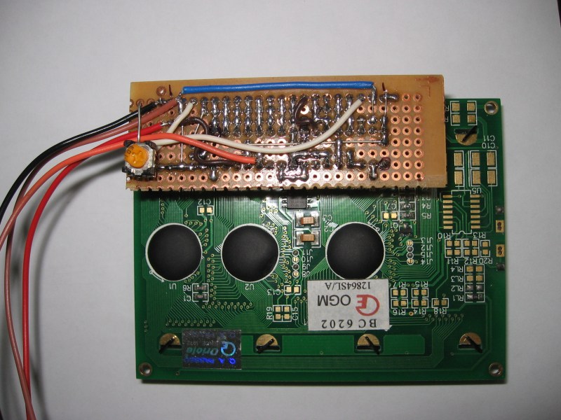
[Debraj] wrote in about his 2-wire serial backpack he developed for a Graphic LCD screen. It’s build on a hunk of protoboard and uses a pair of 595 shift registers to translate incoming serial data to the parallel interface which is used by the LCD screen. It takes more time to push commands this way, but the interface is still quite snappy as you can see in the clip after the jump.
The real trick here is how the hardware has been configured to get away without a third wire for latching the shift registers (if you need a primer on 595 chips check out this feature). The idea of using a latch is that all of the data can be shifted in over the serial pin before it appears on the output pins. Otherwise, the GLCD would see each bit as it shifts into the register, wreaking havoc on its communication protocol. [Debraj] gets around this by using a diode AND gate trick he learned from this other serial LCD project.
One good thing about this method is the 595 chips have a wide range of control voltage that will allow you to drive this with 3.3V or 5V microcontrollers. But you do need to implement the communication protocol and push those commands via serial. For nearly the same cost in chips something like an ATtiny2313 could be substituted to make an even simpler addressing scheme — or even switch to 1-wire protocol. But you’d then lose the wide input voltage tolerance.


It’s not hard to control a (SIPO) latched shift register with just one line and some careful timing, a short drop of the line causes 1 to be entered, a medium drop of the line causes a 0 to be entered and a long drop of the line causes the data to latch (and a zero to be entered). Disadvantage is that you do lose 1 bit (the last bit is always zero).
If you google for “Shift1 system for 1-wire shift registers” you’ll find the details about how to do it. For the arduino users, search for shiftreglcd123 for an implementation of controlling an LCD from a shift register with 1 wire control (or 2, or 3, depending on your choice).
Sounds a lot like asynchronous serial :)
How about multiplexing the power and data on two wires?
Doable for sure, but it would not spare an i/o pin on the controlling MCU.
Technically it would be possible to use just two wires both for power supply and controlling signals, but again the increased complexity would only help to save two wires.
Or you can just burn a PIC and make it even smaller or even translate the nasty protocol to something more reasonable.
I accept that, even use 1 wire (+ 5V, GND) using the UART. But only addition is that we need to put separate code for the PIC and also source the PIC. With the 74HC795, there is no software to be written and the IC is available in local market..
I’m a non-electronics enthusiast here, but I see a couple more than two wires in that picture.
I think black and red are power and gnd. They’re needed anyway so they don’t count!
I explained that in the video about the other 2 wires. As Greenaum mentioned, they are power and GND and are essential (not counted)..
Am I the only one that’s been getting headaches from whatever motion compensation people are using on their videos of late?
This is an excellent hack :D
I had one heck of a time with the hd44780 LCDs out there…
Took me a month just to get them working right with a PIC18F…
I never ventured into the graphical LCD arena, since the text only hd44780 was such a nightmare.
This backpack
The same Trick is described in Elektor EN 2008-05 “Two-wire LCD”
Or Elektor DE 2008-05 “2-Draht-LCD”
You can get the german Article here: http://www.cczwei.de/index.php?id=atm18_download
Nothing really novel.
Controlling a 74595 with one wire and a couple RC circuits is, rather ingenious:
http://www.romanblack.com/shift1.htm
This serial interface , can be used Arduino? Thanks for reply..