One of the acronyms you may hear thrown around is DDS which stands for Direct Digital Synthesis. DDS can be as simple as taking a digital value — a collection of ones and zeroes — and processing it through a Digital to Analog Converter (DAC) circuit. For example, if the digital source is the output of a counter that counts up to a maximum value and resets then the output of the DAC would be a ramp (analog signal) that increases in voltage until it resets back to its starting voltage.
This concept can be very useful for creating signals for use in a project or as a poor-man’s version of a signal or function generator. With this in mind I set out here to demonstrate some basic waveforms using programmable logic for flexibility, and a small collection of resistors to act as a cheap DAC. In the end I will also demonstrate an off-the-shelf and inexpensive DDS chip that can be used with any of the popular micro-controller boards available that support SPI serial communication.
All of the topics covered in the video are also discussed further after the break.
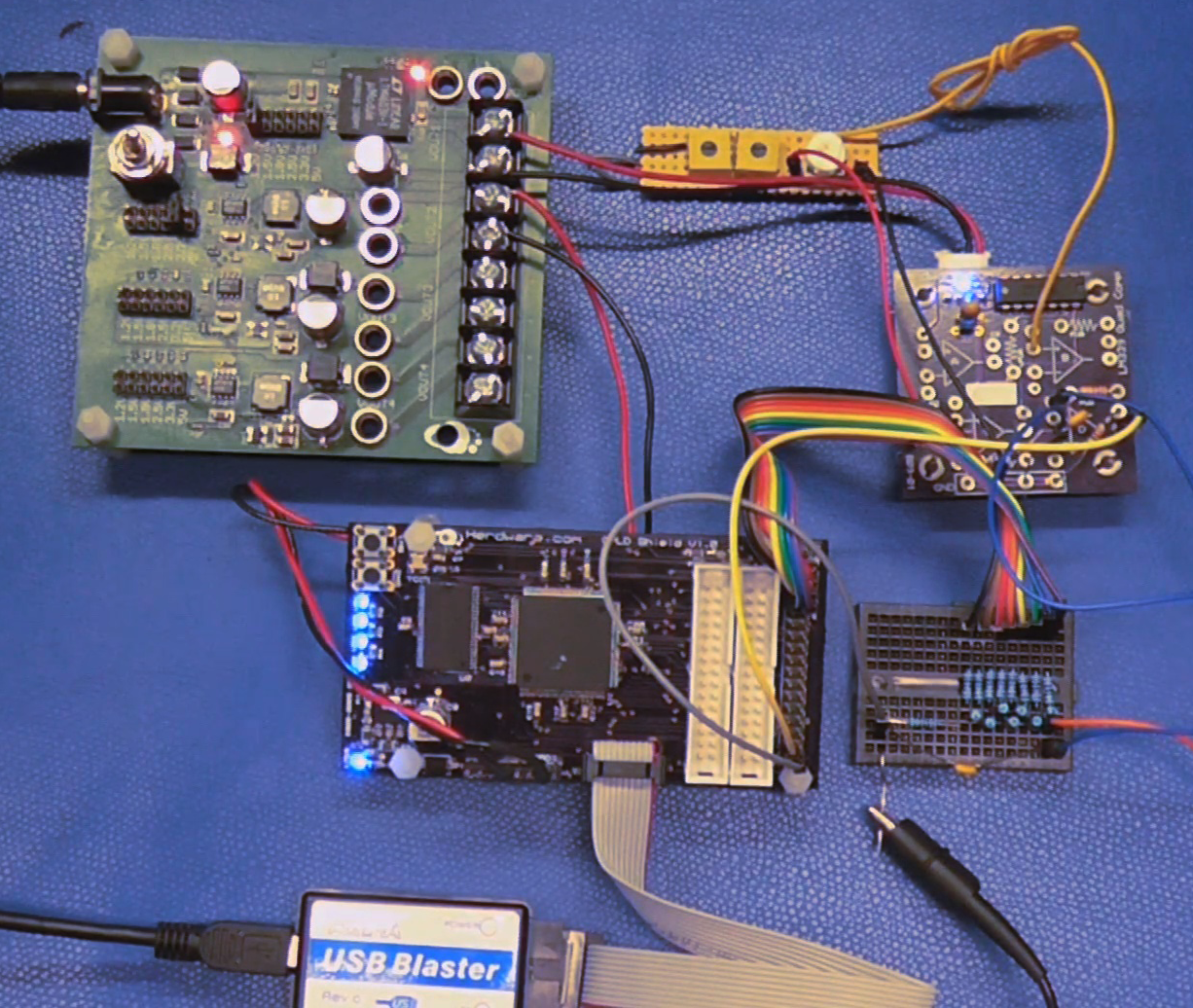
I chose to use Programmable Logic (PL) to build the various circuits as it was quick to configure and didn’t require very much construction while being extremely flexible. It also didn’t require any software programming, IDE, target processor board, etc. This might be an interesting project for you if you are interested in learning or exercising some basic Programmable Logic skills, here I use Altera’s free Quartus II Web version and an inexpensive programmer clone. For the first couple of examples I am using a Complex Programmable Logic Device. (CPLD)
Basic Signal Generation
Creating waveforms can also be done with dedicated logic, for example a CD4060 oscillator/counter can be used instead of the PL counter or also a microcontroller with I/O ports could be used. Note that the microcontroller version does better the more assistance it gets from dedicated peripherals such as a timer or a timer/counter that reloads without waiting for the processor to respond and reset it.


Here are two waveforms created with a simple counter and resistors organized as an R/2R ladder. As the output of the counter increments in binary, the resulting voltage divider created by the interconnected resistors and outputs creates consistent steps between each of the counts; 256 in this case due to 8 outputs being used. Taking the most significant bit also demonstrates a symmetrical square wave.
Building Different Signals is Easy
If the counter were to count downwards upon reaching its maximum count instead of resetting to zero, then a triangle waveform would be generated. So far that’s three waveforms using just a counter and some resistors.


On a slightly different topic, using just some I/O lines, an R/2R ladder, and an analog comparator (ala LM339) a basic type of Analog to Digital Converter (ADC) can be made. Don’t misread this, we were talking about going from digital to analog before but now we’re talking about going from analog to digital.
To describe it simply, a processor or digital counter is connected to the R/2R ladder which is connected to the input of an analog comparator. The voltage to be measured is then connected to the other input of the comparator and then the counter proceeds to count up until the R/2R ladder voltage equals or exceeds the voltage being measured. At that time the comparator trips and the equivalent digital value of the analog voltage being measured is represented by the counter value feeding the R/2R ladder.
Assuming that the voltage to be measured is somewhat stable, the process can be repeated to track the voltage as it (slowly) changes or the count can be reversed until the comparator clears and then reverses. This might be useful for measurements such as monitoring a battery voltage level, etc.
While continuing the use of an adjunctive comparator, a simple voltage to frequency converter can be made by having the counter change directions when the comparator trips. This is not a perfect converter (nothing I do is perfect, life and engineering is a compromise) as very notably the amplitude of the triangle waveform changes in amplitude, but a full voltage square wave would be easy to generate.
Basic Principles for Sine Wave Generation
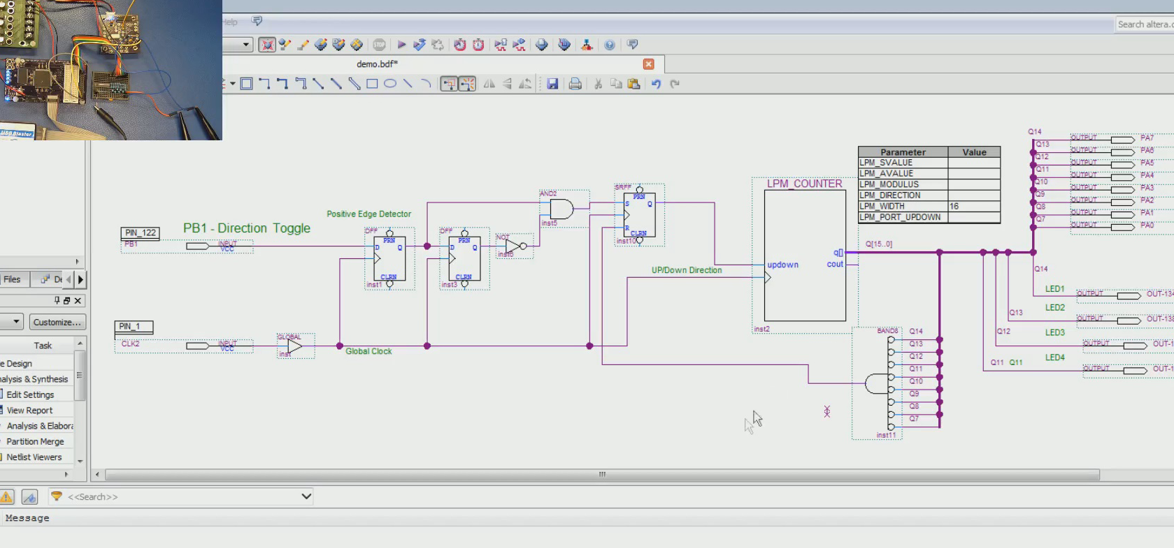
Finally we can create a sinewave through the addition of a look-up-table that contains the appropriate data to approximate a mathematical sine function. A look-up-table (LUT) is simply a piece of memory such as Read Only Memory (ROM) in series with the data, in our case the incrementing counter represents an incrementing address, and the data output is the result of a pre-calculated Sine table.
For this I have switched to a Field Programmable Gate Array (FPGA) which has better internal memory and the ability to initialize the memory with the contents of the Sine table I created for the LUT. In the schematic for the interior of my FPGA the LUT can be seen off to the right just in front of the output pins.
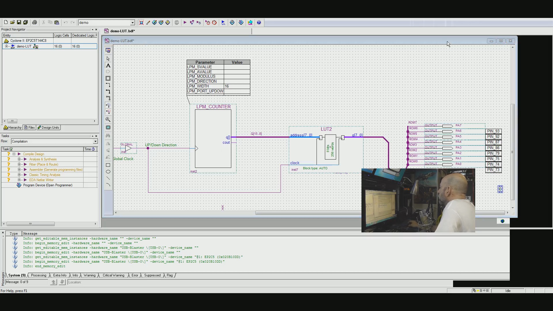
Programming Complex Waveforms
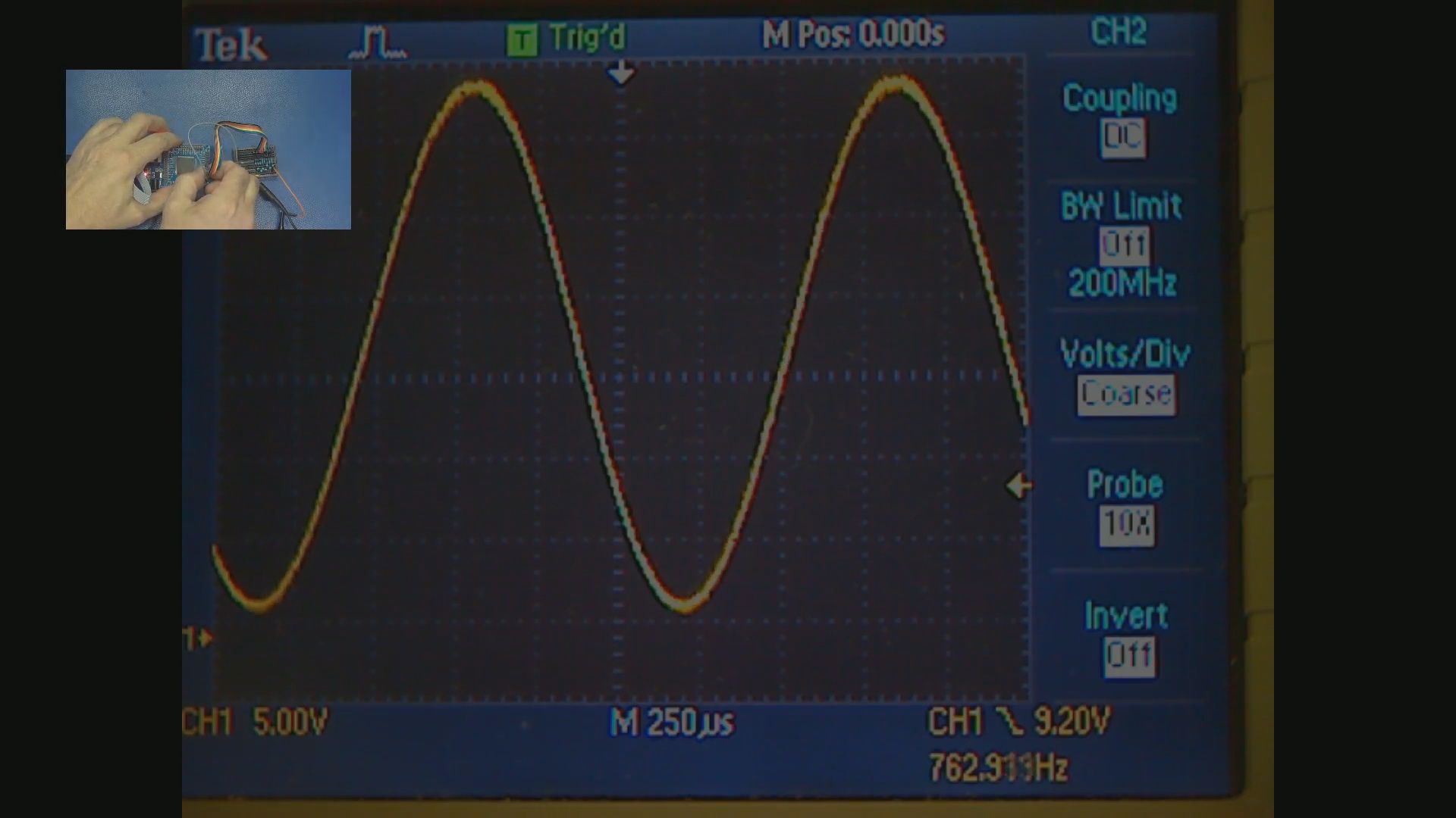
One advantage of a Sine wave created by DDS is that it can be generated at a wide range of frequencies and keep its same shape (low distortion).
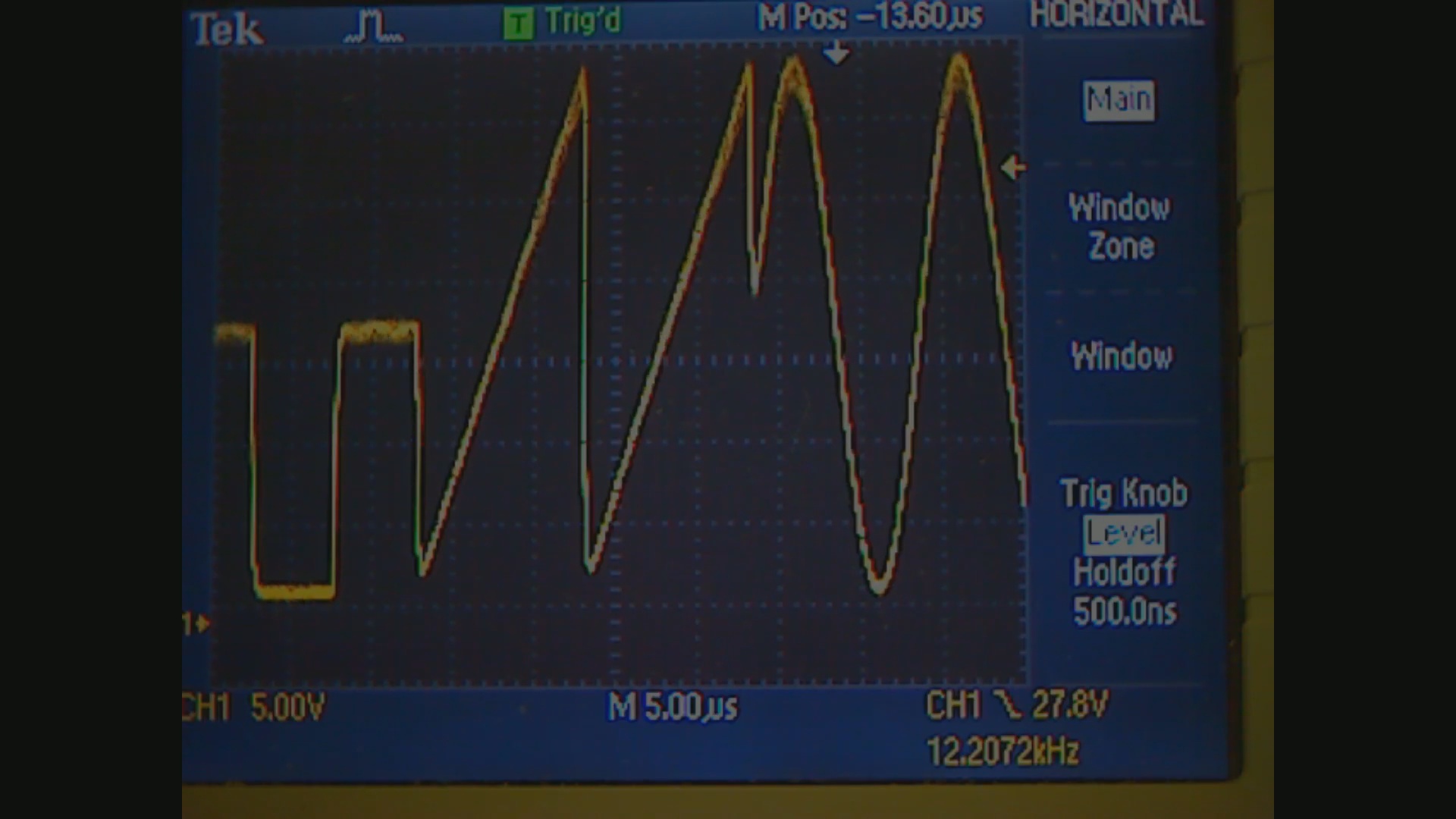
Just for fun and to demonstrate something that can done easily with DDS I created a non-symmetrical waveform. Looking carefully you can see two cycles of square wave, two of ramp and then two of sine wave. Any waveform that can be “drawn” in memory can be created this way.
Other DDS Hardware Options
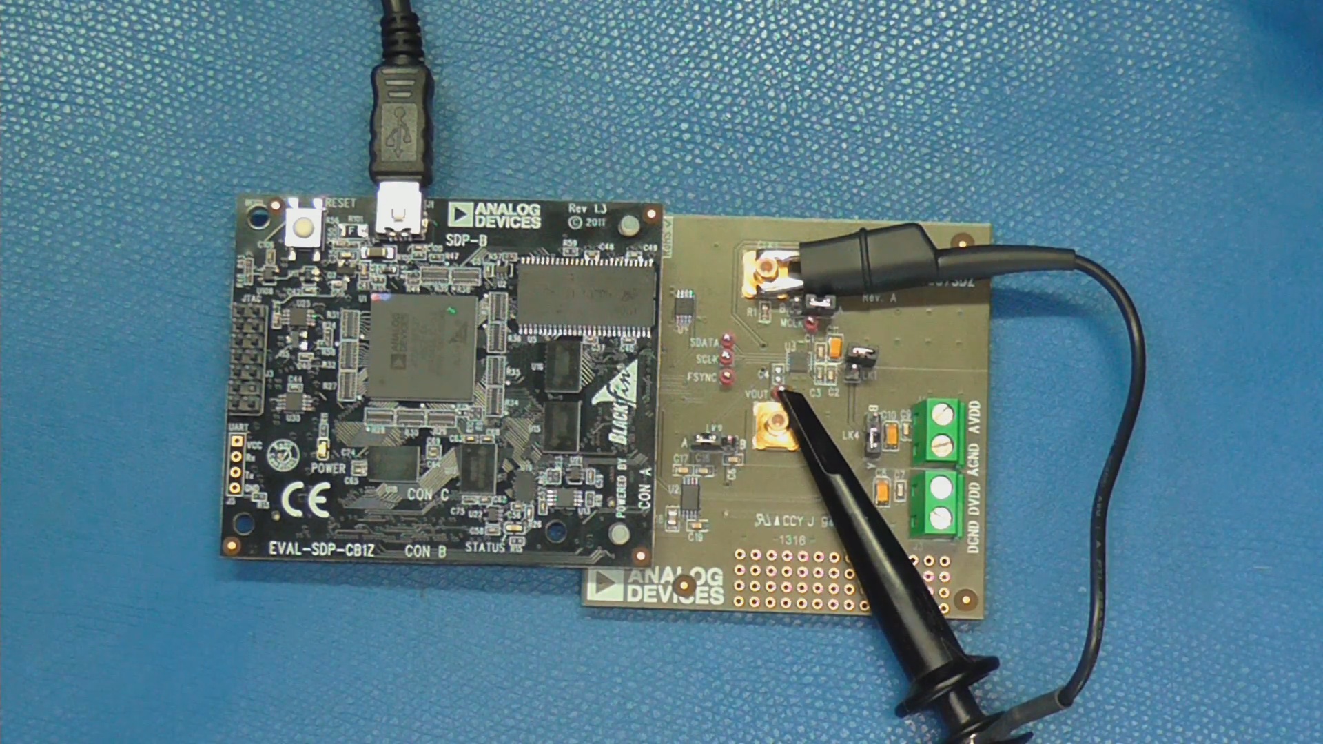
And finally, if you need a DDS without the muss and fuss of making it out of components yourself, there is a selection of DDS components available that are low cost and accurate. Shown here is an Analog Devices 9387 in an evaluation board from the manufacturer. It is SPI serial interface driven and so can be connected to most available single board controllers.
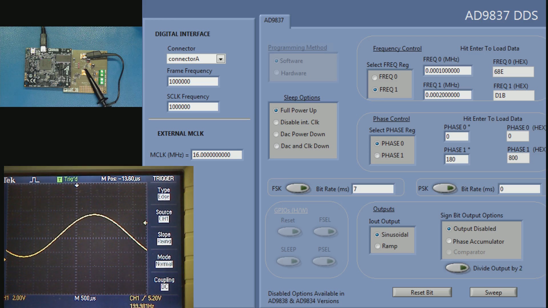
Varying the frequency and phase of a signal by microprocessor control is integral to a DDS system. The software that comes with the evaluation the board shows that two frequencies and two phase offsets can be stored allowing Frequency Shift Keying (FSK) and Phase Shift Keying (PSK) as well as sweeping between two frequencies. This is a useful capability, for example the frequency response of a circuit such as a filter can be observed by sweeping a frequency on the input and then measuring the output on an oscilloscope.
Go Deeper
If you want to know more about DDS there is a lot of information available on manufacturer’s websites and the Internet. Advanced topics to search for include embedded sub-modulation and use with phase lock loops to reduce phase noise, up-conversion using multipliers, and other synthesis circuits used in RF telecommunications.


I’ve been doing something similar in minecraft. A counter that goes up and down at variable speeds with some processing to add 2 waves together. I also have the ability to shift phase.
http://img.photobucket.com/albums/v191/legofreak1988/minecraft/oscope_zps53cfd4ff.png
This site need a voting system… :)
+10000 internets to you
What the holy hell and where is the writeup
I made a forum post about it here.
http://forum.openredstone.org/showthread.php?tid=4547
just…. wow! another 10000 internets from me :)
Please give a download link to the map, this is too epic not to want.
This is on a server. mc.openredstone.org i think the version is 1.7.9
“/warp rekdir” will take you pretty close to it.
openredstone.org for more information about the server.
Thanks
The intarwebs is now completed.
Pretty impressive!
I can’t wait for the day someone makes a full computer on minecraft capable of running itself!:)
Nice post! And very timely, since I’m currently working on a DDS-based project.
Nitpick: It’s an acronym, not a mnemonic.
Ack, fixed. I have a friend who owns a company named Mnemonics and so I knew my internal rulechecker for that word was already compromised; or in this case actually broken. Thanks!
Nitpick of your nitpick: It’s an initialism, not an acronym
http://www.differencebetween.com/difference-between-acronym-and-vs-initialism/
lol. I only approximate the English language anyways.
Nitpick: It’s an initialism. Acronyms are pronounceable, but no one cares so don’t change it.
A couple of day ago after watching Dave’s extended video on the Jim Williams’ pulse generator I started to wonder if that the trick with the length of coax in place of a capacitor might be used in a wicked fast switched capacitor filter. – Could the coax be used as a delay/buffer line? Could you add/subtract a waveform on it, like a mixer? Is this a job for the ‘RF amplifier’ breed of transistors, such as the MMBF5485, since op amps don’t seem to be all that fast? And what use could one find for a piece of kit that awesome, appropriate or not?
Heh, I have an MF-10 I was going to talk about switched capacitor filters at some point. Staying away from the true RF applications for a minute and realizing that I haven’t read the article you’re talking about; the capacitance represented by an unterminated piece of coax can be a fairly complex animal. On one hand it can look like two conductors of unequal size with a dielectric, but the nature is really more of a distributed LRC, LRC, LRC chain where L is the inductance of the conductor and R the DC resistance and then C is the capacitance at that point. Treating a coax as a single capacitor is a lump sum technique and is sometimes modeled that way when accuracy near that point isn’t as important. The reality is that as long as there is an AC waveform being applied, the voltage measured at one end of the coax and the voltage at the other only coincide for brief periods of time.
So yes a Coax is a delay line, where the initial propagation speed is the Velocity Factor as a portion of the speed of light. Different frequencies will travel down it at different rates however and things get spread out on longer runs (phase group delay) and also frequencies get attenuated at different rates. Coax amplifiers used to pre-emphasize the signal to account for some of this.
Picture hanging an RCRCRCRCRC network off of your switched cap filter as a brief example of the complexity of a longer piece of coax.
Ah, so they sort of chirp. Makes sense. =)
Dave’s video on Jim Williams’ pulse gen: https://www.youtube.com/watch?v=uBYMePUFinQ
Would love to hear more about these filters. It’s pretty cool that you can tune them with just a clock rate. Apparently you can even make allpass filters with them. Hmm…!
For anyone in this thread suddenly realizing they don’t have a super complete understanding of transmission line behavior and impedance and stuff, this is profoundly good reading:
http://www.ibiblio.org/kuphaldt/electricCircuits/AC/AC_14.html
In the case where your final objective is to generate a sine wave or whatever at a high power level, you can skip the DAC and use some form of PWM to run the output stage. I have even done it with a dsPIC and had it vary the output in real time in order to maintain a constant V/Hz ratio (at a variable voltage and frequency) for driving motors.
For those of us with a Parallax Propeller, here is an easy way to test it out: http://obex.parallax.com/object/688
Yes there is a whole lot to be said for PWM (making a note for later videos). Anyone can correct me on this, but PWM requires a further conversion in the form of a filter (pole) and filters like to involve time (the recent past and the immediate future) so that the output voltage at any moment can be complex to calculate. PWM’s really shine in power applications as you mention because the output device gets to stay (mostly) completely on or off. I go into this a fair amount in the safe area operation video where I was first trying to learn to make videos. (very dry but the math should be good)
On my blog there is also a small introduction, check it out ;)
http://www.barth-dev.de/knowledge-corner/dsp/direct-digital-frequency-synthesis-ddfs/
Cool blog!
wow, great to hear such a thing from the Commodore-God!
Thanks!
Another great video, Bil! Can’t wait to see the PWM one (or whatever your next topic is). If you want something a bit more challenging than your usual bench experiments (which there’s nothing wrong with, don’t get me wrong), I would love to see something on the theme of a VFD built to drive a single-phase induction motor (such as a shaded-pole fan motor). These are extremely useful – and, thus, expensive – devices which I’ve always wanted to try hacking together at home. My main use would be as a replacement for my CNC mill’s noisy, underpowered, series-wound, spindle motor. Another good application would be in the drive-train of a small electric vehicle.
I’d also like to see this, and I’ve looked into building one in the past. Unfortunately I found out that most variable frequency drives are more than just PWM based sine wave generators. They sense how much current the motor is using and use a control algorithm to determine when to turn on which IGBTs and more importantly when to and which ones to turn off. AC motors are very inductive loads and as such simply cutting power generates massive voltage spikes that can destroy the switching elements. If the control isn’t perfect, failure is also catastrophic as the IGBTs blown due to the voltage spike tend to ‘fail short’, shorting out the VFD output and causing the rest of the IGBTs to be destroyed as the smoothing capacitors dump their charge.
I’d still like to try making one and I’d encourage you to try as well, but I suspect we’d go through a lot of expensive power devices as we worked out the kinks! Any suggestions Bill?
Wow, I haven’t found any of that kind of info during my research, so thanks for that. I had no idea they were so involved, which is why I’ve always wondered why they were so costly.
Of course, other than efficiency, there’s probably no reason not to use the simplistic version, if it’s built right (safety features, good components, proper overhead, etc.).
I saw a guy on YouTube using Audacity, a huge audio amp, and a Variac wired in reverse (used as a step-up transformer) to drive a small appliance motor, but, of course, he didn’t have any specs or measurements of any kind…
I agree, simpler is better. Come to think of it, speakers are also inductive (unless they’re piezo) so a large, well designed audio amp could probably drive a small motor without too much trouble. Anything large enough to be a spindle motor though might be too big for most amplifiers. Part of the problem is that a motor’s inductance actually changes based on it’s speed and load, whereas I don’t think speakers do very much. I don’t quite remember how all the various types of electric motors behave, but I think when most electric motors are under load or started from a standstill, they have a lower inductance and thus draw a lot of current. When running at speed with no load, they have a high inductance and draw relatively little current. The IGBTs (or whatever switching devices are used) should only be turned off when no current is flowing through them, or at least another path for the induced current exists. Otherwise the inductance of the motor will force the current through the IGBT even if it is turned off, producing whatever voltage necessary to make that happen.
I remember finding a few electrical models of an induction motor online a while back. There are surely ones for other motor types too. At the time though I didn’t know how to simulate a changing inductance.
IMO to call it DDS there has to be a phase accumulator included, to generate arbitrary output frequencies.
A common pitfall, which I’ve personally hit (while developing the waveform generators in the Teensy Audio Library), involves the need to bandwidth limit the waveform lookup table when using it to generate higher frequencies of non-sine waveforms. Without bandwidth limiting, sub-sampling the waveform causes aliasing of the higher frequency components which result in low frequency distortion on the output.
This may not be intuitive if you merely think of DDS as pulling numbers from a table. It’s unfortunate the article doesn’t at least mention this common pitfall, but hopefully this comment will help anyone who tries to make such a project. If you use a large table for a non-sine waveform and sub-sample it for higher frequency output, you will run into this problem if you don’t properly bandwidth limit the table for use in the frequency range you’re generating.
Can you clarify what you mean by “bandwidth limit” in this context?
Your lookup table should be low-pass filtered such that when played back at your highest speed there is no frequency components that are exceed half the playback sample rate.
For example if your lookup table is 0,0,0,0,0,0,0,0,255,255,255,255,255,255,255,255 repeated 16 times, and you output one sample in 16 end up with all 255s or all 0s,depending on where you start in the table.
You can get around this by using a polyphase digital filter to effectively upsample, filter then downsample your signal in one hit, but it involves a lot of math.
Isn’t that already impossible, per Nyquist?
No. According to Nyquist, if you decimate (eg, sub-sample) a signal with frequencies higher than half the sample rate of the new, lower output rate, those frequencies alias to become other (really, really undesirable) frequencies in the output.
This is common pitfall. It’s easy to overlook, which is why it’s good to mention in articles like this.
There is in the last example with the AD device I believe. I would also bet that phase-adjusted values can be stored in the LUT depending on what you are doing. The counter version was to get used to the idea before moving on.
“IMO to call it DDS there has to be a phase accumulator included, to generate arbitrary output frequencies.”
Strictly no, a DDS can use one of several methods. But I agree with you that in a traditional sense, one thinks of a DDS as having a LUT and phase accumulator. This is not emphasized in this tutorial at all – and therefore I feel it does not do the subject (or the audience) justice.
So did he hack his head or his glasses to make them stay up like that? My glasses are always slipping, so I’m interested in that hack.
Good article. The “AD9387” tag at the bottom of the article should be “AD9837”.
Added
Bill I want to take a 14V DC output voltage from a battery charger and turn its output into a variable frquency square wave . Frequency being from about 5 hertz to about 100Hz. How would you go about this? The amperage must still be full charger output ie 5 amps.
Hello Bill,
I would like to create a sine modulated PWM. How should I start and I need the frequency in MHz range
Thanks