A UV Lightbox For Curing Prints

With resin printers slowly making their way to hackerspaces and garages the world over, there is a growing need for a place to cure these UV resin prints. No, they don’t come out of the machine fully cured, they come out fully solid. And no, we’re not just leaving them in the sun, because that’s not how we do things around here.

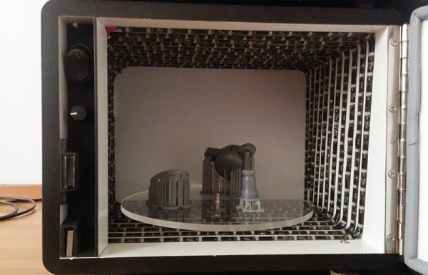
[Christopher] whipped up a post-cure lightbox meant to sit underneath his Form 1 printer. It’s made of 1/2″ MDF, with adjustable feet (something the Form 1 lacks), a safety switch to keep the lights off when the door is open, and a motor to rotate the parts around the enclosure.

The light source for this lightbox is 10 meters of ultraviolet LED strips. The LEDs shine somewhere between 395-405nm, the same wavelength as the laser diode found in the Form 1 printer. Other than a bit of wiring for the LEDs, the only complicated part of the build was the motor; [Christopher] bought a 2rpm motor but was sent a 36rpm motor. The vendor was out of 2rpm motors, so a PWM controller was added.

It’s a beautiful build that shows off [Christopher]’s ability to work with MDF. It also looks great sitting underneath his printer, and all his parts are rock solid now.

Hacking The Crayola Digital Light Designer

[Harry] wrote in with his hack of the Crayola Light Designer. The Light Designer is a pretty unique toy that lets kids write on a cone-shaped POV display with an infrared light pen. [Harry] cracked one open and discovered it has a spinning assembly with a strip of 32 RGB LEDs for the display and a strip of photodiodes to detect pen position. These were ripe for the hacking.

The spinning assembly uses several slip ring connections to send power and data to the spinning assembly. [Harry] connected a logic analyzer to several of the connections to determine which lines were clock, data, and frame select (the strip is split into 2 16-led “frames”). He went on to reverse-engineer the serial protocol so he could drive the strips himself.

Instead of reverse-engineering the microcontroller on the product’s PCB, [Harry] decided to use a Leostick (Arduino Leonardo clone) to control the LEDs and spinner. He mounted the Leostick on the shaft of the spinning assembly, and powered it over the slip ring connections. After adding some capacitance to make up for noisy power from the slip rings, [Harry] had the POV display up and running with his own controller. Check out the video after the break to see the hacked POV display in action.

Continue reading “Hacking The Crayola Digital Light Designer”

Chicken-powered Pendulum

Every once in a while we get sent a link that’s so cute that we just have to post it. For instance: this video from [Ludic Science]. It’s a wind-up chicken toy that kicks a pendulum back and forth. No more, no less.

But before you start screaming “NOT A HACK!” in the comments below, think for a second about what’s going on here. The bird has a spring inside, and a toothed wheel that is jammed and released by the movement of the bird’s foot (an escapement mechanism). This makes the whole apparatus very similar to a real pendulum clock.

Heck, the chick toy itself is pretty cool. It’s nose-heavy, so that under normal conditions it would tip forward. But when it’s wound up, tipping forward triggers the escapement and makes it hop, tipping it backward in the process and resetting the trigger. The top-heavy chicken is an inverted pendulum!

And have a look, if you will indulge, at the very nice low-tech way he creates the pivot: a bent piece of wire, run through a short aluminum tube, held in place by a couple of beads. Surely other pivots are lower-friction, but the advantage of using a rod and sleeve like this is that the pendulum motion is constrained to a plane so that it never misses the chicken’s feet.

Our only regret is that he misses (by that much) the obvious reference to a “naked chick” at the end of the video.

Continue reading “Chicken-powered Pendulum”

Simple Thermal Imager With A Lepton Module

[Andrew] designed a simple thermal imager using the FLIR Lepton module, an STM32F4 Nucleo development board, and a Gameduino 2 LCD. The whole design is connected using jumper wires, making it easy to duplicate if you happen to have all the parts lying around (who doesn’t have a bunch of thermal imaging modules lying around!?).

The STM32F4 communicates with the Lepton module using a driver that [Andrew] wrote over a 21MHz SPI bus. The driver parses SPI packets and assembles frames as they are received. Images can be mapped to pseudocolor using a couple different color maps that [Andrew] created. His code also supports min/max scaling to map the pseudocolor over the dynamic range present in the image.

Unfortunately the Lepton module that [Andrew]’s design is based is only sold in large quantities. [Andrew] suggests ripping one out of a FLIR ONE iPhone case which are more readily available. We look forward to seeing what others do with these modules once they are a bit easier to buy.

Central European Computer Collecting

During Hackaday’s short trip to Czech, we were lucky enough to run into someone who had recently had one of his projects featured on Hackaday. It’s [Martin]’s multi-target IDE for 8-bit CPUs, written entirely in JavaScript, and a full development suite for anything with a 6502, 6800, 6809, Z80, 8080, and 8085. [Martin] was kind enough to sit down and give us the scoop on why he’s interested in old computers, and why he developed his 8-bit IDE project, ASM80.

[Martin] grew up in the days of computer magazines, and originally wanted to build his own computer. That plan didn’t work out, but his parents did get him a Speccy in 1986, but the love of old hardware is still there. Over the years, this evolved into computer collecting, with the old ZX Spectrum, an Commodore 64, ORICs, and Acorns rounding out his collection. As we learned at the Computeum, there the middle of Europe had computers that just aren’t seen on the English-speaking Internet, and [Martin]’s collection is no exception.

In addition to doing some very cool stuff for some very old computers, [Martin] also donated something to the Hackaday Hackaspace. It’s a PMI-80, a single board computer made for university computer science students, and basically a KIM-1, but based on a Czechoslovak clone of the Intel 8080 made by Tesla. There is 1k of RAM and 1k of ROM on this board, a calculator keypad, and a few seven segment displays. For the time, it was a great ‘student’ computer, and not really rare in Europe, but this is the first one I’ve seen on my side of the Atlantic.

You can see some pics of the PMI-80 below with [Martin]’s interview. [Martin] also promised to write-up a short history of classic central european computers, a subject there isn’t much written about in the anglosphere. We’ll post a link to that when he finishes that up.

Continue reading “Central European Computer Collecting”

Direct Digital Synthesis (DDS)

Direct Digital Synthesis (DDS) Explained By [Bil Herd]

One of the acronyms you may hear thrown around is DDS which stands for Direct Digital Synthesis. DDS can be as simple as taking a digital value — a collection of ones and zeroes — and processing it through a Digital to Analog Converter (DAC) circuit. For example, if the digital source is the output of a counter that counts up to a maximum value and resets then the output of the DAC would be a ramp (analog signal) that increases in voltage until it resets back to its starting voltage.

This concept can be very useful for creating signals for use in a project or as a poor-man’s version of a signal or function generator. With this in mind I set out here to demonstrate some basic waveforms using programmable logic for flexibility, and a small collection of resistors to act as a cheap DAC. In the end I will also demonstrate an off-the-shelf and inexpensive DDS chip that can be used with any of the popular micro-controller boards available that support SPI serial communication.

All of the topics covered in the video are also discussed further after the break.

Continue reading “Direct Digital Synthesis (DDS) Explained By [Bil Herd]”

Fixing Ghost Touch In The OnePlus One

The OnePlus One is the flagship phone killer for 2014, available only by invite, and thus extremely cool. So far it’s a limited production run and there will, of course, be problems with the first few thousand units. When [vantt1] got his One, he noticed a few issues with the touch screen. Some touches wouldn’t be registered, typing was unpredictable, and generally, the touchscreen was unusable. [vantt] had seen this before, though, so with a complete teardown and a quick fix he was able to turn this phone into something great.

[vantt] realized the symptoms of a crappy touchscreen were extremely similar to an iPad mini that had recently had its digitizer replace. From the Foxconn plant, the digitizer in the iPad mini is well insulated from the aluminium enclosure. When the screen and digitizer are replaced, the cable connecting it to the rest of the iPad can come in contact with the case. This leads to the same symptoms – missed touches, and unpredictable typing.

Figuring the same cure will fix the same symptoms, [vantt] tore apart his OnePlus One and carefully taped off the digitizer flex cable. Reassembling the phone, everything worked beautifully, and without any extra screws in the reassembly process. You can’t do better than that.