Working with high voltage is like working with high pressure plumbing. You can spring a leak in your plumbing, and of course you fix it. And now that you’ve fixed that leak, you’re able to increase the pressure still more, and sometimes another leak occurs. I’ve had these same experiences but with high voltage wiring. At a high enough voltage, around 30kV or higher, the leak manifests itself as a hissing sound and a corona that appears as a bluish glow of excited ions spraying from the leak. Try to dial up the voltage and the hiss turns into a shriek.
Why do leaks occur in high voltage? I’ve found that the best way to visualize the reason is by visualizing electric fields. Electric fields exist between positive and negative charges and can be pictured as electric field lines (illustrated below on the left.) The denser the electric field lines, the stronger the electric field.


The stronger electric fields are where ionization of the air occurs. As illustrated in the “collision” example on the right above, ionization can happen by a negatively charged electron leaving the electrically conductive surface, which can be a wire or a part of the device, and colliding with a nearby neutral atom turning it into an ion. The collision can result in the electron attaching to the atom, turning the atom into a negatively charged ion, or the collision can knock another electron from the atom, turning the atom into a positively charged ion. In the “stripping off” example illustrated above, the strong electric field can affect things more directly by stripping an electron from the neutral atom, again turning it into a positive ion. And there are other effects as well such as electron avalanches and the photoelectric effect.
In either case, we wanted to keep those electrons in the electrically conductive wires or other surfaces and their loss constitutes a leak in a very real way.
Round Surfaces vs Sharp Points
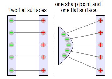
The electric field in the air can be made strong by the geometry of the wire or surface. Look at the illustration on the right and compare the two cases. One has two flat surfaces facing each other and you can see the resulting field is relatively weak all over. But in the other case one surface has a sharp point and the resulting field is strong near that sharp point. So that sharp point is a candidate for a leak. The flat surface need not be flat. Just rounding out a sharp point to make a rounded surface can often go a long way.
Where do you get sharp points? An obvious location is the sharp end of a wire, or the multiple sharp ends of a stranded wire. Those can exist where two wires are joined by twisting them together. In the photos below you can see the same wiring going to a high voltage capacitor but on the left the lights are turned on, and on the right the lights are off, making the leaks clearly visible as a bluish corona. The corona that appears as a jet is where two stranded wires have been twisted together. The connection has been wrapped in black electrical tape and you can see it clearly doesn’t help.


You can also see another source of sharp points in the above photos. The capacitor is two square copper plates separated by multiple polyethylene sheets. The copper plates are thin and so the edges automatically constitute a sharp point. Sure enough, there’s plenty of visible corona, or leakage, around the top plate. A thicker plate with well rounded corners would be an improvement since the resulting electric field would be weaker.
Perhaps the most unexpected culprit is a small diameter wire where even along its length it can act as a sharp point. The clearest case is that of a lifter where that corona jet is used to produce lift and make the lifter fly. Below you can again see the same thing with the lights on and off. In the lifter, a triangle of thin wire is separated from an aluminum foil skirt which are electrically at opposite polarities. Notice that the foil also has leakage, mostly at the corners but also along its length. Efforts have been made to make the top edge of the foil rounded by folding it around supporting horizontal balsa wood sticks. However, sparks happened between the wire and the foil and those sparks blew holes in the foil. Those holes have sharp edges and account for most of the leakage you see in the foil.


Insulating Against Leaks
Your first line of defense against high voltage leakage should always be to avoid sharp points or edges. That’s literally fixing the problem at its source. However, if you can’t do that or if you can and just need more help, then you can add insulation.
As you saw above, electrical tape is not always effective, and at these voltages, isn’t all that great a solution anyway. Tape doesn’t make a great fit with sharp edges or points. Instead, better solutions involve coating the surface with a liquid that’ll harden, forming a close fit with the surface. Perhaps the best insulation is corona dope, available in electronics stores. As the name suggests, corona dope is a coating that is specially designed for this purpose, preventing or reducing the bluish corona. When air-dried, the corona dope in the photo has a breakdown voltage of 2200 volts/mil, and 4100 volts/mil if heat dried. The breakdown voltage is literally what it sounds like, the voltage at which the material breaks for a given thickness. 2200 volts/mil means that a 1 mil (1/1000th of an inch) thick coating will break down at 2200 volts. A coating that’s twice as thick can handle twice the voltage, and so on.


Another coating I’ve used is wax. Paraffin wax can be bought in large quantities in art stores, and wax for canning purposes can be bought in grocery stores. In the photo below I’ve melted the wax on a stove and am pouring it into a capacitor mold. (EDIT Make sure to use a double boiler when melting wax. Put the pot with wax in it in a second pot boiling water. Always observe the process in case all the water boils away.) I’ve even made the electrical connections in small cylindrical containers like bottle caps and filled them with wax. I’ve also use miscellaneous epoxy resins, whatever I happened to have at the time. With both those you can make quite thick layers. In the photo below you can see a resin capacitor where I’ve gone overboard and even coated the sides with wax.


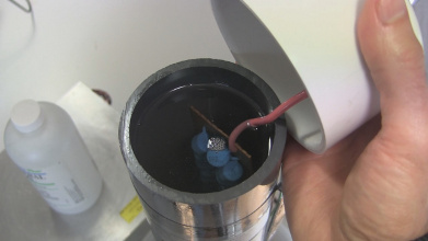
Yet another insulating technique is to immerse the connections, or indeed entire circuit boards in an oil, in my case mineral oil. Shown here is a high voltage power supply where the entire Cockcroft-Walton voltage multiplier board is immersed in mineral oil in a PVC pipe. I bought the mineral oil in individual 500ml bottles from a drug store.
Doesn’t wire have insulation on it? It does but breakdown voltage applies to that insulation too. You can buy wire that’s specially made for high voltage and has a high voltage rating. Open up an old CRT type computer monitor and you’ll see a thickly insulated wire running up to the cathode ray tube. The metal wire itself is only around 18 gauge and the remainder is all insulation.
 going into CRT")

Staying Away from Ground/Other Polarities
But as explained above, the electric field exists between two polarities. If you have just a wire running from your high voltage power supply to your device then where’s the other polarity? The table the wire is sitting on can act as the other polarity. I’ve had wires running across a tabletop with not all of the wire in intimate contact with the table, and the moment the power supply was turned on, any sections of wire that were a little off the table surface showed visible attraction to the table. The wires actually moved. The wire with its circular cross section is sharp compared to the flat table and so, as in the above diagrams, the electric field is strong near the wire. If the strength is sufficient to ionize air and the insulation has too low a breakdown voltage than the wire will leak.
This situation is not limited to tabletops either. With a strong enough electric field, objects in the surrounding room can provide the other polarity.


As shown in the photos above, I solve this problem by suspending the wires in the air, creating transmission lines. I sit the wires on plastic pill bottles, glass jars, anything that’s a non-conductive material. In the photo on the left above, the high voltage wires going to the lifter (see the top-left corner of the photo) are sitting on a pill bottle and a glass container. The ground wire, however, is on the right, and as you can see on the far right, is allowed to touch the side of the table. The photo on the right shows a bunch of high voltage resistors raised in the air on plastic pill bottles during the prototyping stage while making a high voltage probe.
But don’t those bottles and jars play the same part as a tabletop? Not if the tabletop has some electrical conductivity. I find a laminated tabletop is a fair non-conductive surface, but if there’s dust or moisture on it, which there often is, then it becomes conductive and can act as the other electrode.
Making Good Connections
There are two ways I make connections. One is to give a lot of rounded surface area to the connection, giving lots of room for the charges to spread out, resulting in weak electric fields. The other is to minimize sharp edges while insulating.
For example, I collect roundish metal balls and make threaded holes in them for bolting to (see the photo below on the left). Just keep an eye out in stores for metal balls. Drawer handles are one source. I’ve also cut pieces from half inch diameter copper rod and filed and sanded them to a rounded shape (third from the left in the photo.) Connections are then made by wrapping the wire around the threads of the bolt and tightening the bolt. I’ve also gotten into the habit of getting rid of the sharp wire ends by putting ring connectors on them. To standardize I make #20 1/4″ threaded holes and use short matching bolts from the hardware bins at Home Depot and then use 12-10 AWG 1/4″ ring connectors.


As shown in the photo on the right above, for the insulated connections approach I strip the ends of my wire and solder on short pieces of copper tube from hobby stores. I’ve found they fit snuggly into 16-14 AWG butt connectors. I also wrap electrical tape near the ends of the wires, enough to snuggly fill the ends of the butt connectors.
For a less custom approach you can search for various connectors available in your area. I like my approach where all wires end in cylindrical connectors and then connections are made through a butt connector because that eliminates any mismatched connector issues you’d have if you ended up with two female connectors that you needed to connect or two male connectors.
Type of Wiring
I’ve already talked about the issue of thin wires acting as sharp points, and so wire thickness is something to consider. I’ve also mentioned the issue of breakdown voltage of the wire insulation. In my case I long ago stocked up on 16 AWG stranded wire with an insulation that gives an outer diameter of 1/8″. The insulation thickness helps but the material is also a consideration. Mine is just randomly selected and is some form of rubber. But I was able to buy copious amounts of it off of a roll and it’s held up fairly well, though I have seen it leak along its length when the insulation was slightly damaged.


Another type of wire I’ve seen in use in high voltage applications but have never used myself is ball chain. I guess the round balls eliminate or minimize the issue of sharp points, mimicking a large diameter wire. I assume these would still require suspending them as a transmission line. If you’ve experience with these please let me know in the comments what you’ve done and any tips or issues to be aware of.
And that’s how I wrangle high voltage to get as much voltage and current as possible to where I want it. My record with high powered, high voltage DC is a measured 85kV conducted across a room with no leaks that I could find, that is, after I ran around like a plumber plugging them all.
Have you wrangled high voltage? If so, please let us know any tips or tricks you use. These gems of high voltage knowledge are hard won and we all want to hear about them. As always, it’s not just success that is interesting. What issues have you run into while trying to bend the electron flow to your will?


Another article today that hits too close to home. I work on high voltage power supplies for a living. Ones the size of several, full size refrigerators stacked side by side (one single cabinet) and others that literally fill rooms. These have not only massive amounts of finely regulated high voltage available, but high current as well.
I would run you out of town for about 9/10ths of the “tricks” you use. You or someone influenced by you is going to kill themselves. Pity that.
Corona “dope” is probably fine for sniffing, not much else. unless you are using it on low voltage and building it up by hundreds of coats…
Butt splices on HV wire? seriously? Do you solder your ring terminals? Though you shouldn’t normally, with HV you always solder them… and ball your solder…
And your flat plates… think about the edge of that plate, on two sides of that edge there are what? sharp corners….. Better revisit what you say about sharp points…
And you don’t have to collect metal balls and then try to drill a hole in them (something you fill most likely fail at, and I hope you’re bright enough not to be holding it in your hand when the bit breaks or slips) – you can purchase corona balls. they are a “thing” you know…
Ball chain? Unless that shit is being stretched and arcing and losses aren’t your concern, seeing how there is only a contact connection going on between each “ball”… I guess if making weird HV resistors is your kink…
toroidal shapes, using copper pipe instead of wire, G10, slotted G10, etc etc etc…
Most of you reading, please don’t. Just don’t.
Re the corona dope, I gave the breakdown voltages, but you’re right, it doesn’t take much math to realize it would take a lot of layers to handle tens of kV.
Regarding the butt splices on HV wires, as I said in the post, this has worked great for me up to 85kV measured. By measured I mean with a high voltage probe and that was holding a charge on a homemade HV capacitor.
Regarding the flat plates, I point out the issue of the edges in the post and show a photo of the leakage at the corners.
Drilling the holes in the metal balls is simple. Put them in a vice with rubber on either side. Either start your drill slow to make an initial mark and then gradually speed it up or use a punch to make an indent and then drill. Multiple steel balls, including the one shown in the photo were done that way with no slipping and with no more difficulty than would be had with drilling a flat piece of steel. However, thanks for pointing out that you can buy them. I wasn’t aware of that.
As always, not everyone means exactly the same thing by the terms they use. Me? When I say “high voltage” I mean anything I can’t touch with my bare hands without getting a zap. Meanwhile, you obviously spend your time with some real big boys’ toys, and when you say “high voltage” you mean something that can fry you to a crisp from across the room.
The author is dealing with quite respectable voltages, however I’d wager he’s dealing with far higher impedance power supplies than you work with. Likely high enough that if they do arc to something, they’ll do a fairly limited amount of damage and probably won’t kill you instantly. So while I don’t doubt your advice, maybe you’re being a little harsh.
(However, while you’re in harsh mode, do you feel like writing up a basic “don’t die” list for someone with a spare microwave transformer who’s thinking of making some Lichtenberg wood etchings a la https://hackaday.com/2015/09/19/making-lichtenberg-figures-in-wood/ ? I do plan to start by setting the gear up outside and only turning it on from the safe end of an extension cord several meters away. :)
That should be off a “roll”, a role is a position… like right now I’m playing the role of nitpicker. ;-)
Oops. The nit is now fixed. Thanks for picking. :)
maybe you can add some info about the cut-outs or voids (what’s the right word?) on pcb’s so that creepage does not happen, or minimizes it.
many of us have seen those cutouts, know what they are for, but are not certain how to create our own (how much void to leave, where they should be on the pcb, what shapes work best, and WHY, for each of those questions. what does a pcb designer ask themself when AC is on the same pcb as lower voltage DC, for example? maybe some examples to show good, better, best and even the other direction?
tia
http://www.pcbtechguide.com/2009/02/creepage-vs-clearance.html
You would use a table for the *minimum* creepage requirement vs the working voltage based on what type of environment your circuit is supposed to be in. When you can’t leave enough space on the PCB due to component density, then you start looking into cutting slots to *increase* the distance.
Remember kids, DO NOT run traces between optoisolator intended for isolation. The space is there for a reason. (see first illustration)
Damn, hackaday! Your illustrator is awesome.
(Just had to say that. The “Excalibur” one also rocks!)
2nd; I’ve been liking your illustrations, HAD. good job. give that guy a raise ;)
I strongly support this opinion. :D
Joe Kim! We like him a lot. :)
And after many requests, we started posting his art in the original resolution. Save your favorite images, use them as desktop background. You know we do. That one from the 2nd Omnibus is just too cool.
(http://store.hackaday.com/products/hackaday-omnibus-2015)
Where from I can download the full HaD art collection, please?
It’s not complete, but our illustrator has a project up on .io
Thank you very much!
The threaded hole into a ball with wires tightened on using a bolt seems counterproductive… that bolt has a hex head and I see a bunch of sharp points!
Needs some silicone caulking on it.
We want the sparks where they belong! :)
I’ve wondered the same thing but I guess those corners aren’t as sharp as they seem. Back when I used to just wrap bare wire around the threads I’ve had problems, but never with the bolt heads.
Does US use mil instead of thou for any reason other than to confuse people working in mm?
Although it can be fun to feign incredulity when you ask what size something is and they say xx mil as a short for millimeter.
I was just in South America, and in Spanish 1000 is mil. Strange to me as an English speaker because I want to auto-associate that word with million.
Mil is also a Swedish/Scandinavian word for the distance of 10 kilometers. We usually say it’s 50 mil between x and y instead of 500 kilometers. Took me a while to unlearn the habit of thinking of distances in miles….
when you are heat your wax “on the stove” use a double boiler!!!
never, ever, ever put a pot of wax, pitch, tar or anything that can burn “rapidly”, directly on a hot plate or especially, a burner.
wax is especially bad for this!
put your pot of wax in another pot of water
Yo dawg
It’s way better to “Xzibit” the double pot then to have to deal with burning wax. Apart the obvious fire and chance for it to spread, burning wax like this will create soot, which is a pain in the ass to clean off of everything…
Also, you can’t locally overheat (and thus char) the wax, makes cleaning the pot a lot easier ;-)
Good point re melting wax. I added a caution to the post.
Your figure showing the sharp surface against the flat surface is probably in error. Are both surfaces metal? If yes, the static electric field should be NORMAL to the surface of the metal; if it were not, charges in the metal (good conductor) would move accordingly to make sure that is so. To satisfy this boundary condition, the field lines must be CURVED. That, in turn, can give you a good idea of the shape of the field lines and the equipotential surfaces, which are normal to the field lines. With that in mind, you can imagine that if your figure is redrawn correctly, the density of field lines at the sharp corner (vertex) will increase.
Today, such a problem can be easily solved numerically on a computer. In the old days, a special kind of paper, called “teledeltos” was helpful in solving field problems. Hackaday had an article on that: https://hackaday.com/tag/teledeltos/
The gif shows what are called isolators or disconnectors. These are not circuit breakers (CB). The difference is that CBs are designed to operate under load, i.e when there is power being transmitted in the line. Disconnectors are not supposed to be used under load. powerplant rated CBs are really expensive (really!). The gif shows an incident where an isolator was opened under load. Only one phase out of the three flashes over.
Wow. Sounds like there are some electricians out there. Im not an hv electrician, but in my off time i play one. Tesla coils are probably my all time favorite hobbies. Most of the things you wrote about are only good for your application at that time. Ive tried most of the ways you wrote about to reduce carona. As the voltages get higher the solutions become more simple or obvious. Atleast to me, things like better connections, less connections, even cooler ambient temps are simpler and basic. Im not going to slam you like some of my electrical brothren did. I just wanted to give you a pointer when it comes to the higher voltages.
As the voltages get higher, the more unpredictable the dangers are. From the types of shoes to the earings you might be wearing, iv found that most things will conduct electricity at some point. Even a piece of burnt fiberglass makes a good conductor.(carbon makes it a reisistor). ….
The pointer is: as the voltages your playing with get higher, take a step back, and evaluate what is going on. Then ask yourself, should i be fu$#@ng with this.
Have a nice day
Your mention of cooler ambient temps is a new one for me. Can you elaborate please?
And, I agree with your sentiment completely. That’s why I like the plumbing analogy I started out with. If anyone’s fixed a leak, then increased the pressure only to find another leak, then they feel the same way. As you increase the voltage, more and new issues pop up. Been there, done that. As I said at the end of the post (maybe I should have put it at the beginning as a disclaimer), I’ve only gone up to 85kV, measured with a high voltage probe and holding in a homemade capacitor with these techniques. I should also point out I’ve done only DC, my only AC experience is with a small Tesla coil. I imagine with bigger Tesla coils you get into all sorts of new issues.