“Chapter 5; Horowitz and Hill”. University students of all subjects will each have their standard texts of which everyone will own a copy. It will be so familiar to them as to be referred to by its author as a shorthand, and depending on the subject and the tome in question it will be either universally loathed or held onto and treasured as a lifetime work of reference.
For electronic engineers the work that most exemplifies this is [Paul Horowitz] and [Winfield Hill]’s The Art Of Electronics. It definitely falls into the latter category of course books, being both a mine of information and presented in an extremely accessible style. It’s now available in its third edition, but the copy in front of me is a first edition printed some time in the mid 1980s.
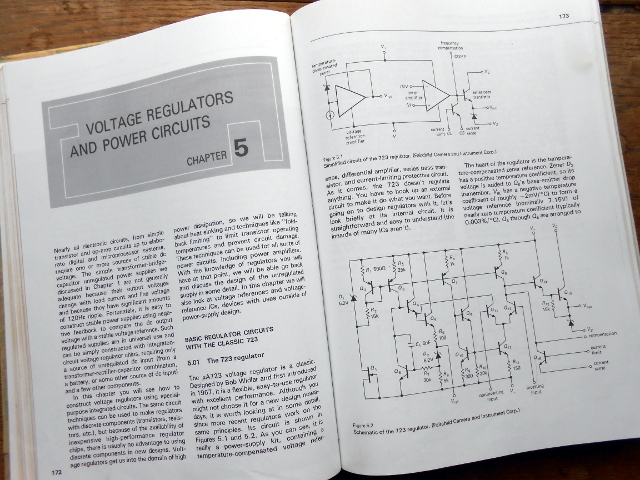
Chapter 5 probably made most of an impression on the late-teenage me, because it explains voltage regulation and power supplies both linear and switching. Though there is nothing spectacularly challenging about a power supply from the perspective of experience, having them explained as a nineteen-year-old by a book that made sense because it told you all the stuff you needed to know rather than just what a school exam syllabus demanded you should know was a revelation.
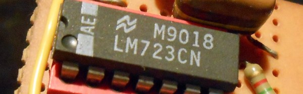
On the first page of my Art of Electronics chapter 5, they dive straight in to the μA723 linear voltage regulator. This is pretty old; a design from the legendary [Bob Widlar], master of analogue integrated circuits, which first made it to market in 1967. [Horowitz] and [Hill] say “Although you might not choose it for a new design nowadays, it is worth looking at in some detail, since more recent regulators work on the same principles“. It was 13 years old when they wrote that sentence and now it is nearly 50 years old, yet judging by the fact that Texas Instruments still lists it as an active product without any of those ominous warnings about end-of-life it seems plenty of designers have not heeded those words.
So why is a 50-year-old regulator chip still an active product? There is a huge range of better regulators, probably cheaper and more efficient regulators that make its 14-pin DIP seem very dated indeed. The answer is that it’s an incredibly useful part because it does not present you with a regulator as such, instead it’s a kit of all the parts required to make a regulator of almost any description. Thus it is both an astonishingly versatile device for a designer and the ideal platform for anyone wanting to learn about or experiment with a regulator.
Continue reading “Get To Know Voltage Regulators With A 723”
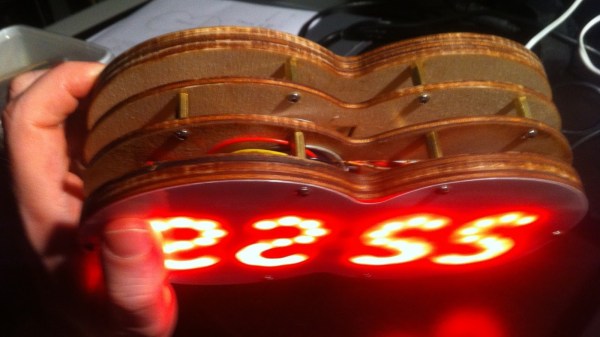
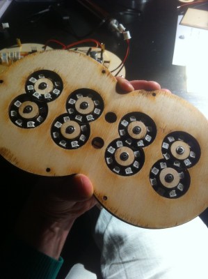 Each digit is made using one pair of Neopixel rings, stacked to form a figure of eight. All the digits are composed of arcs, so readability isn’t the best but it’s not hard either. [rhoalt] does mention that the display is easier to read via blurred camera images rather than visually, which isn’t surprising. We’re long used to seeing numbers composed of straight line segments, so arc segmented digits do look weird. But we wouldn’t have known this if [rhoalt] hadn’t shown us, right ? Maybe a thicker diffuser with separator baffles may improve the readability.