If you have ever ventured into the world of motor vehicles you may be familiar with a dynamometer, possibly as a machine to which your vehicle is taken for that all-important printout that gives you bragging rights (or not) when it comes to its ability to lay down rubber. A dynamometer is essentially a variable load for a rotating shaft, something that converts the kinetic energy from the shaft into heat while measuring the power being transferred.
Most of us will never have the chance to peer inside our local dyno, so a term project from a group of Cornell students might be something of interest. They’ve built a dynamometer for characterising small electric motors, and since their work is part of their degree courses, their documentation of it goes into great detail.
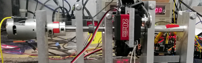
Their dynamometer takes the form of a shaft driving a stainless steel disc brake upon which sit a pair of calibers mounted on a fixed shaft that forms a torsion bar. The whole is mounted in a sturdy stainless steel chassis, and is studded with sensors, a brace of strain gauges and a slotted disc rotation sensor. It’s not the largest of dynamometers, but you can learn about these devices from their work just as they have.
This is a project sent to us by [Bruce Land], one of many from his students that have found their way to these pages. His lectures on microcontrollers are very much worth a look.


Can’t let this go by without mention of an early hacker, a fellow named Joule. Yes, THAT guy.
https://www.aps.org/publications/apsnews/201506/physicshistory.cfm
Typo, “pair of calibers” (.38 and .45?), should be “pair of calipers”.
How do you think they got holes into the slotted disc?
CNCed
I forgot/neglected to put a smiley with my comment.
Too bad their final schematic isn’t shown, but otherwise a nicely illustrated write-up
Sort of like a Prony brake?
I think their use of the brake disc/pad setup is a good idea. I have a similar project in my garage with the disc and caliper from an old Honda Civic for just this purpose.
I like the Prony brake, Its kind of where the term Brake Horsepower originated
https://www.youtube.com/watch?v=-ihYAafWN6Q
Important to note there’s two main types of dynamometer in the vehicle context, inertia dynamometers (which most rolling roads tend to be) and brake dynamometers (which this is a example of).
Inertia dynamometers use a big load in the form of a solid mass of drum and time how long it takes the device under test to accelerate that load to a given rpm. Once you know time vs rpm change, and the mass of the drum is a constant, then you can work out power, rate of change at a instance giving a power curve etc.
Brake dynamometers brake the engine/motor at a given rpm until it cannot accelerate the load any faster, so gives you maximum torque at that rpm. Its a lot less kinder on engines than the intertia type but can be used to set steady state parameters up (in ic context, cruising mixtures etc) and if you want to test durability and ability to hold a given power output without exploding, a inertia pass is pretty useless. I kind of got excited that this was the holy grail type, that controls the motor and sweeps up through rpm points when programmed to do so, only holding the given brake load needed to match the output at that rpm as short at time as possible with a tight pid loop controlling things, but with a simple switch of parameters in software can revert to a traditional long duration power testing rig. This is what modern expensive dyno rooms tend to havem but the controls are all hellishly expensive, and even aftermarket retrofits are outside what I can justify for a tinkerer in a shed.
This isnt the pid controlled type it seems, but thumbs up for quantifying even a straight braked load with strain gauges on the brake anchors. I built one of them into the rear caliper mount of a small motorcycle as a uni project using strain gauges on the torque arm and a commercial modular strain gauge amp from RS years ago now, but it used to overheat the rear brake which was never designed to cope with even 12hp, however now I currently have a large (1KW capable) heenan and froude water brake in my shed, waiting for me to finish building its transmission to a floor mounted roller so it can act as a inertia style AND a static engine on stand test bay. I’ve removed the old manual reaction arm and fitted it with a load cell so I can measure rotational torque in the casting anchor, and I need to get on and mechanise the pid loop and some sort of control to turn the water vanes to automatically bring up the load time at each setpoint, but I am way off finishing it enough to even document whats done statically. Easy to get carried away on projects doing this though :-)
ugh, its 1,000 KW capable, lost a order of magnitude doing the conversion from BHP into KW in my head sorry…
Don’t blame you, wish everything was just measured in Watts.
I just drank a Watt of Water!
B^)
I just bought a Watt of cookies for a Christmas party!
If you want a beefier brake, I would suggest a dynamic brake from a semi truck, they can be had for the price of scrap (still not free though, lot of copper in there). All you have have to give it is a couple of volts at a few watts to control the magnetic field it and a steady base.
Alternatively, a thick disk of aluminium and use either a moving permanent magnet or electromagnet to induce eddy curents, cut up microwave oven transformers make nice and cheap electromagnets.
I am curious as to why they used a brake for this kind of test. Why not a 3 phase motor(Brushless DC motor) with a variable resistor could be made work and the output would be easily graphed via some microcontroler analog input through a shunt measuring amps and a voltmeter measuring volts.
Exactly… Why the brake – indeed? IMO A Prime-Mover to calibrated Generator-Load makes for a far better test bed. Calibration is accomplished by replacing the Prime-Mover under test with a well characterized spin-up then release rotating mass. Precision test-beds can be oriented vertically through horizontally. With reasonable care the vertical test-bed orientation gives best-case results by minimizing bearing loss. The vertical results are compared with the horizontal (or other angle, if-possible) results to reasonably characterize bearing loss alone.
If I was the Cornell advising Professor overseeing this student investigation, I would have sent them back to the drawing-board before realizing this project.
Because the torque cannot be measured with what is essentially an eddy current brake, unless the braking motor is mounted on some sort of floating lever arm setup with a loadcell (like an engine dyno water brake). That would be even more complicated to implement than a friction brake. Torque data is as important as power and efficiency here, since the purpose of the project is to inform the powertrain design of an Shell Eco Marathon vehicle.
To measure rotational Torque you don’t need external physical “load cells” etc. when you have a calibrated electronic rotational load (which is ideally the same as the prime mover which adds differential measurement elimination). Torque is a force (F=m*a). You know the equivalent mass imposed by the electronic rotating load, you also measure the acceleration by the change in rotational velocity (RPM) when the load is applied. Careful control of the load allows for both quasi-static Torque measurement. Otherwise, deterministic dynamic Torque measurement is a given. Am I wrong?
I think you are over simplifying the torque measurement here by a lot… the equivalent eddy current load is not a constant or even linear relationship to angular speed and input current, so unless you map out a parametric operating region the torque cannot be quantified. Which essentially requires another dyno for doing just that. Look up pictures of eddy current brake dyno on google, theres a reason none of them use your method and all use the loadcell lever arm instead.
@Onehunglow,
I appreciate your reply and indeed I may be missing some key factors. I’m going to give this more thought.
But for now I still feel physically and electrically mirroring the prime mover with an identical load that is fully characterized over a broad operational range of rotational parameters simplifies matters significantly. Differential drive-measurement of an identical DC mover-motor-generator-load pair should provide improvements in both precision and accuracy. This is how “pre-distortion” parametric tables are defined for use in high efficiency production DSP driven motor systems.
Your typical three phase motor is in now way a brushless DC motor. They are induction motors at least 90% of the time, and those are quite a pain to use for generation.
The rc hobby has them being built in the 1-2KW range for next to nothing, not only that but most of them are running permanent magnets. Prime for being used as generators. Most of them are decently built as well. My .02c.
I was curious about that too – seems like the drag would increase as the pads and disk heated up. Using a BLDC geared up from the motor’s rpm would provide a pretty easy method of measuring consistently. You would just output each phase to a variable resistance?
Because the brake applies force against a load cell, and that’s the only thing you need to calibrate. Mass standards are easy to come by. Once it’s calibrated to a known good standard, then you can verify that calibration with any mass you have hanging around.
Electric motors don’t have a linear efficiency curve, their efficiency may change with temperature, and so on.
BLDC motor =/= AC motor
please stop calling it a 3 phase motor…it’s a DC motor with a removable solid-state commutator, very different from an AC motor
My solution was to connect an electric motor to the output shaft and use back emf through a variable resistance and a meter to get a relative reading. I also experimented with adding reverse voltage and adjustable parallel plates with large magnets. Ended up turning it into a nice high current homopolar generator.