A few summers of my misspent youth found me working at an outdoor concert venue on the local crew. The local crew helps the show’s technicians — don’t call them roadies; they hate that — put up the show. You unpack the trucks, put up the lights, fly the sound system, help run the show, and put it all back in the trucks at the end. It was grueling work, but a lot of fun, and I got to meet people with names like “Mister Dog Vomit.”
One of the things I most remember about the load-in process was running the snakes. The snakes are fat bundles of cables, one for audio and one for lighting, that run from the stage to the consoles out in the house. The bigger the snakes, the bigger the show. It always impressed me that the audio snake, something like 50 yards long, was able to carry all those low-level signals without picking up interference from the AC thrumming through the lighting snake running right alongside it, while my stereo at home would pick up hum from the three-foot long RCA cable between the turntable and the preamp.
I asked one of the audio techs about that during one show, and he held up the end of the snake where all the cables break out into separate connectors. The chunky silver plugs clinked together as he gave his two-word answer before going back to patching in the console: “Balanced audio.”
Differences Balance
I didn’t really know what balanced audio was back then, at least from an electrical point of view. I’ve since learned what the difference between balanced and unbalanced audio is and why balanced audio is the way to go for pro audio applications.
The first and most obvious difference between balanced and unbalanced audio is that while an unbalanced line, like that RCA cable behind my stereo, has two conductors — signal and ground — a balanced line has three conductors. A clue to what’s going on lies in how the conductors are labeled. There’s a ground conductor, of course, as well as two input conductors, generally labeled “IN+” and “IN-” but often referred to as “hot” and “cold” respectively.
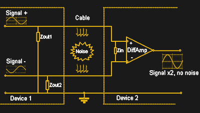
These two wires carry audio signals that are identical except for polarity — the cold line carries an inverted version of the signal on the hot line. This looks like the perfect setup for a differential amp, and that’s typically what lies behind the jack on pro audio gear, although transformers are sometimes used instead. The differential amplifier outputs the difference between the hot and cold signals, which gives the audio signal amplified by a factor of two.
The noise rejection trick comes from the fact that both the hot and the cold lines are balanced, or have the same impedance referenced to ground, which means that any noise that makes it into the cable will be added to both lines equally. Since this will increase the voltage on each line by the same amount, the differential amp will subtract out the noise on the receiving side. Here’s a good demo of how it works using an audio mixer app.
Crosstalk and Phantoms
Common-mode noise rejection is not the only benefit of balanced audio. Another one is the cross-talk reduction offered by the twisted-pair hot and cold lines canceling out each other’s electromagnetic field. This ends up being really important in those thick snakes with dozens or hundreds of channels snuggled up against each other. There’s also noticeably better performance at the higher audio frequencies in long cable runs if the audio is balanced.
Another advantage of balanced audio circuits is the ability to overlay a DC bias voltage between the hot and cold circuits and the ground line. This is often called phantom power and can be used to power microphones at the other end of the line. For pro audio gear, 48-VDC phantom power is typical, and a switch is generally provided at the connector on the audio console to control whether a mic gets power.
As for the hardware at the end of that audio snake that long-ago day, it fairly bristled with the de facto standard for pro audio connections, the XLR or Cannon plug. The XLR has been around since James Cannon, after whom the connector gets its other name, invented it in the 1950s. The XLR has proved itself a sturdy and reliable connector that can handle almost anything, from audio inputs to connecting speakers to amps and even DMX digital lighting control.
[Featured images: Neutrik AG, Sweetwater]


And this is why industrial stuff still uses RS422 for data a lot.
Yep.
And magnetic disks. On a trolley. Slowly barged through corridors. Still beats any bandwidth.
DMX lighting uses EIA-485 which is derived from EIA-422; eg. the other ‘snake’. Same principle only digital data instead of balanced audio.
EIA-485 is also a proper multi drop network protocol rather than P2P.
Although I haven’t read the standard, I’m pretty sure 485 is not a protocol but rather just physical layer specification upon which a multi drop protocol can be layered.
Correct, it doesn’t specify the logical protocol. Bad choice of words, there. However, unlike EIA-422, the physical layer specification allows for multiple drivers by using tri state logic.
And USB and Ethernet and …
And lets not forget the Telephone the start of 600 ohm balanced audio (POT)
A transformer still has some advantages, like galvanic isolation, near perfect common mode rejection etc. And a high end low distortion audio transformer can be surprisingly expensive. The way I was taught to remember which is which in the cable is XLR stands for SXreen(1), Live(2), Return(3)
I’ll have to remember that one….
DI Boxes still contain transformers. Galvanic isolation is much appreciated in stage environments. Most of the linear distortions (aka “filter effects”) get corrected using EQs. Non-linear distortions are rather uncommon with audio transformers. It’s just coils and some ferrite or mu-metal, but still much more expensive than semiconductor solutions.
Transformers do have some advantages. But ICs, like That Corp’s THAT1583 are hard to beat. Very low noise, distortion. As a disclaimer – I knew these guys a long long time ago before they were THAT.
I like that’s semis a lot. IMHO if you are going to use a semiconductor solution they are the way to go. However, a transformer gives you beautiful voltage gain with no noise. BTW, before they were that, were they this? (;
This, That, cute, but no –
They were engineers at dbx. That’s where I knew them. Back in the 70’s.
Yeah, the durability issue means HDMI isn’t going to make it to road equipment any time soon.
There is two wire HDMI, well really 3 including ground,then there’s this… am skeptical of it though https://www.youtube.com/watch?v=TZXxr6BbACo , as well as HDMI over CAT5, the latter is what I’am used too. but it is a converter, it’s really HDMI to IP so there is loss but works find on PTP CAT5 setup.
There is actually a ton of DVI/HDMI in live entertainment. Most of the big LED screens are driven by DVI, which is then converted to another proprietary (generally ethernet based) protocol for transmission to the panels. Fiber is used on HDMI for long distance runs, so that negates the need for a balanced signal.
And the CAT 5/6 cable that the Ethernet based proprietary protocol runs on uses balanced twisted pair transmission.
HDSDI – Surely if it wasn’t for DRM and the device control elements of HDMI we could have had that instead. BNC on a single coax. Way more bomb proof. How many times have we all had an HDMI cable crap out or just fall out of the gear. Don’t even start on ‘TOSLINK’ as a connector standard…
Oh god TOSLINK lol. I thought it was great when it first came out then….
Totally agree. Good ol BNC keeps it tight and right and is even spray-resistant.
It’s been a long time since I’ve heard them called Cannon connectors. I’m glad I’m not the only one.
Multicore “snake” cables like that are becoming a rarity though, with the advance of digital systems that can push it all through a bunch of lightweight, thin and cheaply replacable ethernet lines…
Not on stage. Not yet.
Latency, reliability, compatibility, pricing and fixability (solder iron…) are the factors.
Depends on budgetary circumstances I’d say. There’s plenty reliable solutions with tolerable delays, but they are not cheap. As for the soldering iron, well, you would not use one, you’d just toss out the cable and use another one. It was impossible when the big multicores would be heavy and unwieldy, but with ethernet lines, it’s not even economically viable any more to fix them up. Just replace a broken cable.
Yes on stage. When you change the topology. You can get a stage box that does all of the mixing and no audio gors to the board which is just a control interface. So the ethernet can be just command and control signals, and maybe some meter bridge or RTA data, nothing that has to be truly real time.
When you are dealing with digital gear there is a natural latency in the D/A and A/D stages. Somewhere in the range of 0.5ms. So the 0.2ms or a digital protocol like Dante might add is pretty negligible, and vastly superior in latency then going through multiple D/A stages.
Slower than analog for sure, but the differences only add up to what would be a few feet of travel of a sound wave through air.
Definitely on stage, check out Yamaha’s CL mixer range, only 8 physical Omni in’s and Outs on the back of these desk that have up to 72 mono + 8 Stereo channels. You have to use a Rio box to get the audio data back to the desk which uses the Dante protocol.
Mixing a musical in September with a CL5 and all band and radio mics will be coming back to my desk via Ethernet.
I’m beginning to see big name shows using fiber optics like you’d usually see in server rooms, even though the cables are more fragile.
Fiber optic cables can be very robust, it’s the connectors which are fragile. In times of Dante or AVB, it is simpler and more reliable to send Audio over a Layer 2 Network than over a 200 pair Snake.
At conferences I don’t rig up my own ethernet either. I just use the already deployed Network and have my own VLAN.
Yep. I’ve worked a few shows over the last few years and the “snakes” are four or five thin optical/ethernet lines, these days. None of that multi-line analog stuff anymore.
It’s not just audio. I design ROVs (remotely operated underwater vehicles) and we use differential to send baseband video hundreds of meters with nothing other than a little post-compensation to counter high frequency roll-off. With precompensation you can send even further.
On top of the other stuff mentioned here – the near 0 dBm levels and the usual 600 ohm impedance don’t hurt a bit, especially compared to the millivolt/50k of your unbalanced RCA phono to preamp setup – which probably has more series resistance in that 3 feet of cheapo incomplete-coverage shield (sometimes not even braided) than 100ft of quality snake cable.
That combined with the low level makes things lots worse.
Sure, but mic signals benefit the most from balanced lines precisely because of their low signal levels (-40 to -60 dBv).
The cross-section, twist, and other physical properties of the cable can also affect susceptibility to noise pickup; Standard balanced lines are great; Star-quad has even more interference rejection.
http://www.canare.com/uploadeddocuments/cat11_p35.pdf
I saw a great demo (not a sales demo either) where a guy used an electric drill to induce audio noise into different cables. He had to actually wrap the star-quad cable around the drill before there was audible pickup.
Line level RCA is usually about 1v p-p. The old magnetic phonograph cartridges were millivolt level.
I’ve seen XLR in the use of Power Connectors (ie: The electric scooters sold at K-Mart). Working in Radio, this was the “DE FACTO” connector. In News, we still use XLR for Microphones as well. In house, everything is embedded, so we are slowly going away from the audio issues. I still have a fondness of balanced audio in every project I work in…even radio projects on the side
Mobility scooters and electric wheelchairs use them as well for charger connectors.
4-Pin XLR has been pretty common for power on stage (scroller and LED cable) and broadcast (camera and monitor power) for a while now. I was just looking at it the other day for something and they are rated at like 10A, so it’s not a terrible choice.
But yes, the quality of balanced analog audio is still excellent, it just becomes less attractive where you have multiple A/D and D/A devices in chain. We are already starting to see tours and installs that are all digital now, though. The only analog is the the A/D in the mic pre and the D/A in the poweramp.
Not sure if we’ll start seeing mics with the A/Ds built in for a while, outside wireless systems and the home recording studio, though.
“The XLR has proved itself a sturdy and reliable connector that can handle almost anything”
It was designed back in the day when audio designers believed myths such as single point earths. These days one must deal with much more RF interference (from e.g. phones) and the poor RF shielding afforded by the XLR doesn’t cope well with real world issues faced by contemporary audio designs.
It didn’t help that they were traditionally wired incorrectly, in what became known as the “Pin 1 problem”. There’s even a webpage about it: http://pin1problem.com/
There’s also a “Pin 2 problem” which relates to which of pin 2 and pin 3 is “hot” and what happens when you have an adapter cable for an unbalanced connector (e.g. RCA) and one of pin 2 or pin 3 gets shorted to pin 1. Some drivers cope with that and some don’t.
The other side of what I called the “pin 2 problem” is that instead of connecting one of pin 2 or pin 3 to ground (when interfacing to an unbalanced connector), it may be left open. This may work well, or not so well (due to capacitive coupling to the floating wire) or not at all (if transformer coupling that requires the other wire for return current is used).
BTW, here are some examples of the sorts of heinous adapter cables one may find in the field:
https://www.slideshare.net/JasonDeMoe/how-to-solder-v35
(slide 71 onwards).
I always reference this Rane note for abominable adapters and ground loop avoidance.
https://www.rane.com/note110.html
“It was designed back in the day when audio designers believed myths such as single point earths. ”
Um single-point earthing was and still is a good audio design principle, and I’ve designed and built more than a few audio control rooms whose performance bears this out. The main reason for single point grounding is to avoid the creation of ground loops, which is when a wire’s shield that has been grounded at both ends creates a loop that picks up interference, and this interference is a current flowing on the ground path which can leak or induce the interference int the signal path.
I take your point that these days there’s more RF and digital hash to deal with, but that is more a matter of the quality of shielding and the use of advanced RF-blocking techniques like better equipment enclosures and ferrites, and the benefits of single-point grounding are still valid.
(Back in the day, I got to hear Neil Muncy do his great noise and balance AES presentations)
Yeah. Did a design that was installed about 2km from a commercial FM broadcast tower. Even a run of 50 meters with ‘double’ grounding gave grief. The V/m (volts per meter) was so high it gave all sorts of trouble. Single ground (at the amplifier), and the problems went away.
Knowing that audio matching transformers are pricey, I found that the line transformer in any modern phone, answering machine, or cordless phone works over the full range for me. Free! They do have to stand up to some FCC standard for isolation. I had to put 3 of them into a Digitech pedal effects unit to get rid of whine from it’s switching power supply when it’s used in a self contained powered portable ensemble. The instrument has a pair of isolated outputs built into it, and one on the preamp to effects unit in. Earth is no where in sight, this is portable. But then I am good to go into a PA.
Back online. Squirrels ate my internet connection at the pole. Squirrels!