
Solder is the conductive metal glue that one uses to stick components together. If you get the component and the PCB hot enough, and melt a little solder in the joint, it will stay put and conduct reliably. But it’s far from simple.
There are many different solder alloys, and even the tip of the soldering iron itself is a multi-material masterpiece. In this article, we’ll take a look at the metallurgy behind soldering, and you’ll see why soldering tip maintenance, and regular replacement, is a good idea. Naturally, we’ll also touch upon the role that lead plays in solder alloys, and what the effect is of replacing it with other metals when going lead-free. What are you soldering with?
Intermetallic Compounds
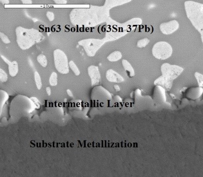
Soldering, and its higher temperature cousin, brazing, are one of essentially two ways create metal-to-metal bonds, and they allow the use of low-temperature techniques that still create relatively stable bonds between two metal surfaces. Soldering is also an interesting chapter in the field of metallurgy, on account of it being based around so-called intermetallic compounds (IMCs).
Welding stands in contrast to soldering, where high temperatures melt the metal on both sides of the pieces that are being joined, permanently fusing them. Welding is a high-strength, high-reliability way of joining metal pieces, but is unfortunately wholly unsuited for delicate electronics where excess heat can damage parts and the goal is more to ‘glue’ electrically conducting elements together than to melt them together.
This also leads us to the reason why soldering and IMCs are such a source of trouble, to the point where IMCs are referred to as ‘evil’. IMCs are essentially bits of the two metal surfaces on either side dissolved into the solder, causing enough of a joining that each side of the joint is more or less stably fused with the solder. Unfortunately such an IMC is a far cry from the stable solid metal of a welding joint, and as a result can be brittle depending on exactly which metals were involved in the solder alloy.
But the IMCs formed in soldering are strong enough, and their formation is at the root of why every solder alloy uses tin. Tin has the property that it is very good at letting other metals dissolve into it. In fact, it’s possible to solder with pure tin, although as we’ll see below, most solder is improved by adding other metals into the mix.
It’s physics all the way down
Solder doesn’t melt itself though, and even the construction of the soldering iron tip has a lot of metallurgy hiding underneath the skin. The tips themselves are composite structures, generally consisting out of a tellurium copper core, plated by a durable iron layer, normally covered with tin for the part that’s supposed to be ‘wettable’ and with chromium for the part below the tip where the solder is not supposed to stick. The iron layer was added to prevent the tin in the solder to dissolve the copper of the tip, which used to be a significant issue.
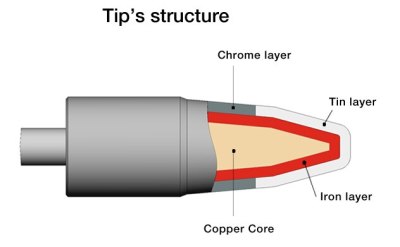
The iron layer is a poor thermal conductor, and should be kept as thin as possible without losing the durability benefits it provides. But because iron rusts, it should be kept covered in a thin layer of tin from the solder.
If one does get iron oxides forming, there are a number of ways to remove this build-up. Essentially this involves abrasive methods to physically remove the oxide layer, or the use of a tip tinner, which generates an acid when exposed to the heat from the soldering iron. This acid is stronger than the mild acid from the flux, so it should remove even the iron oxides. Fresh solder is mixed in with tip cleaner, so the tip is immediately coated and ready to go.
Let’s hear it for eutectic solder
When it comes to that roll of solder people have lying around, rarely more than a cursory thought is given to which alloy it is, and what the exact properties of that alloy are. You might think of solder as “leaded” versus “lead-free”, but there’s a lot more to know than that.
Sticking with lead-based solder for now, a cursory glance reveals that there are quite a number of popular types, along with their melting temperatures, here:
- Sn5Pb93.5Ag1.5 (296-301 °C)
- Sn10Pb88Ag2 (268-299 °C)
- Sn35Pb65 (247 °C)
- Sn5Pb92.5Ag2.5 (287-347 °C)
- Sn40Pb60 (183-238 °C)
- Sn50Pb50 (183-216 °C)
- Sn60Pb40 (183-190 °C)
- Sn63Pb37 (183 °C)
- Sn62Pb36Ag2 (179 °C)
- Sn43Pb43Bi14 (144-163 °C)
The 60/40 and 63/37 blends of tin and lead are most common among hobbyists. An interesting property of some of these alloys is that they are eutectic, meaning that in their phase diagram, all metals in the alloy are matched in their liquid and solid phases: eutectic solders melt completely at a single temperature.
In lead-free alloys, here too we have an impressive list:
- Sn100 (232 °C)
- Sn99.3Cu0.7 (227 °C)
- Sn96.5Ag3.5 (221 °C)
- Sn95.5Ag3.8Cu0.7 (217 °C)
- Sn96.5Ag3Cu0.5 (217-220 °C)
- Sn96.3Ag3.7 (221-223 °C)
- Sn95Sb5 (232-240 °C)
- Sn97Ag0.2Sb0.8Cu2 (220-234 °C)
Here we can see that lead-free alloys do indeed have a higher melting point than leaded solder on average, and there are eutectic and non-eutectic alloys available.
The advantage of an eutectic alloy is that it’s far easier to get a good-looking joint with it. While non-eutectic solder will still work, there’s a much larger risk of defects in the resulting joint, which can lead to cracks and other issues over time. Eutectic alloys, on account of the molecular matrix for all metals in the alloy forming at the same time while solidifying, tend to create highly regular, mechanically and electrically stable joints.
On moving to lead-free soldering
Concretely, when moving from soldering with lead-based to lead-free solder, there are two big changes:
- Soldering with higher temperatures.
- Higher tin content in lead-free alloys.
As this PDF by Kester indicates, the tin in solder joins not only to the solder joint, but also dissolves the copper and iron in the tip itself, which is why tips eventually wear out. A tip that is designed for 63/37 lead-based solder will consequently not last as long when used with lead-free solder such as Sn99.3Cu0.7 or Sn95.5Ag3.8Cu0.7 because the iron plating will dissolve into the tin significantly faster.
Vice versa, issues can also crop up. While one can use a soldering tip that’s rated for lead-free alloys with lead-based alloys without issues, it is never a good idea to use that tip afterwards for lead-free soldering. Traces of lead can get into the lead-free solder and disrupt both the way the latter melts and then solidifies, likely causing faulty, unreliable joints.
Whiskers and health implications
While talking about lead-based solder metallurgy, it’s hard to avoid the twin gargantuan elephants in the room: the health implications of lead and the formation of tin whiskers. A previous Ask Hackaday article already touched upon this recently. The health implications are easy enough to summarize: lead is one of the few substances where there’s no amount that can be considered to be safe. Lead bio-accumulates in the body, and it’s paramount that lead-contamination is avoided in the workplace through cleaning of any contaminated surfaces.
As for the vapor produced while soldering – whether lead-free or lead-based – this will not contain any lead, but it does contain the heated flux vapor, which in the case of rosin produces colophony. This is a complex mixture of gases and particulates which have been found to be irritating to the human respiratory system, damaging lung tissue in the process.
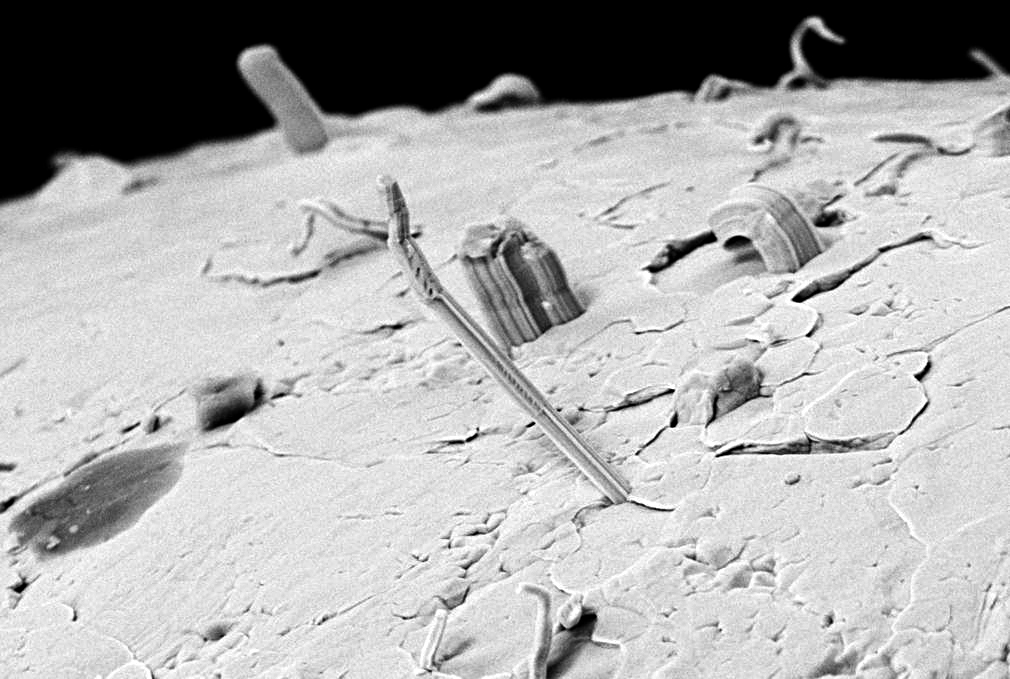
The formation of tin whiskers has been a major topic, long before the move to lead-free solders. Unfortunately the formation of whiskers in metallurgy is a poorly understood phenomenon, with the usual explanation involving compression strength causing the growth of these whiskers. While the addition of lead to tin-based solder helped to reduce the growth of whiskers, it is not a complete fix.
The application of a conformal coating, or the use of specific alloys, can help limit the formation of tin whiskers. It should also be noted that it’s not just tin that is susceptible to whisker formation, other metals are also implicated. Until we better understand the physics behind it, preventing it means hitting upon that right alloy formation by sheer luck.
Wrapping up
While we have a great time soldering, it’s also an entry into the science of metallurgy, and even beyond. But after reading this, we hope that you give your solder alloy a little more thought, and keep your tip rust-free and tinned whatever is your blend of choice. And we’d love to hear any tales you have of tin whiskers.


I want to use lead-free solder with my TS-100. Do I need a different/ special tip and which variant of solder should I use? Sn96.3Ag3.7?
Where I work, we’ve had more success with doing lead-free soldering if we don’t contaminate the soldering process (i.e. dedicated lead-free tips, keeping any solder-wick ribbon specifically for it), still the same shape though.
It was okay to do lead-based solder rework on previously lead-free (as manufactured) boards so long as you didn’t then try to go lead-free as that would risk messing everything up with high chance of dry-joints.
As for blends, we appear to have Sn96.5Ag3Cu0.5 and Sn99Cu1 but I’ve no idea what the ‘flavour of choice’ is with the people who do use it the most.
I’m using one for more than 3 years now for hobby (not extensive use). TS-BC2 tip. I recently ordered a new tip, because the old one developed a cavity on it. Still using it (I’m a cheapstake), but the effect of the reduced surface area is obvious. I mostly used SnCu, but occasionally 60/40 too. When I change solder, and want to clean it throughout, I wipe off all solder, apply new solder, repeat 2 times. TS-100 is proven to be a good tool for me.
If you really want to use lead free solder, I would go for the lowest melting eutectic material, Sn95.5Ag3.8Cu0.7.
But in my opinion I would stay with leaded solder for hobbyist use. It’s lower melting temperature, heat capacity and hardness make it much easier to work with. It’s not radioactive :-)
Just don’t eat or lick your solder and let your children play with it.
I think you mean, “OR let your children play with it!”
In terms of picking a solder, there is actually a lot of different types.
Here is a list of some common types: https://en.wikipedia.org/wiki/Solder_alloys
As seen on this list, there is ample amounts of lead free solder that also doesn’t contain 90+% tin. (Some contain no tin at all)
That tin whiskers forms when having a high concentration of tin isn’t an unknown fact. Though, the exact science behind it isn’t all too known. But it isn’t a common property for most alloys and metals. (Whisker growth is actually rather rare.)
Bi56Sn30In14 for an example is a low temperature solder commonly known as ChipQuik’s lead free version.
Bi58Sn42 has had a history of being used in IBM mainframes.
In52Sn48 can solder onto glass, quartz and other typically unsolderable surfaces.
Au80Sn20 doesn’t need flux, though expensive to use due to its 80% gold content.
Cd95Ag5 is a general purpose solder, but contains 95% Cadmium and is therefor not RoHS complaint.
Zn95Al5 good for soldering aluminium.
Though, there is many other examples. But most soldering alloys do contain some amount of tin, but there isn’t a need to pick one that has 90+% tin content. After all, tin isn’t used for its strength, but rather its low melting point. Indium and other metals can technically replace tin in a fair few applications.
Then there also is other ways to make connections, like gold plated pads, and gold plated “springy” bumps on the chip, and simply hold it in place with a bracket. (or any other non corroding pressure assisted connection method) But this is generally not the cheapest approach in most situations, nor the most practical.
The bismuth based solders would be nice, but they tend to be rare as hens’ teeth and expensive when you do find them from a local supplier. Also, the low melting point of 139 C is a little bit too close for comfort for some components like high power high temperature FETs that may run up to 150-200 C.
Apparently, if there’s any lead involved, such as with pre-tinned wires or leads, the combination of Bi58Sn42 and the lead can lower the melting point to 95 C and create very weak and brittle joints that can be pried apart with a toothpick.
And in general bismuth solders have inferior mechanical properties, being somewhat brittle and stiff even when there’s no lead involved.
Completely off topic, but these solder names would make some good passwords :D
Though, they are a bit short to be safe against simple brute force attacks.
But, sixtypercentleadandfourtypercenttin would be a fair bit stronger from brute force attacks.
And fiftyeightpercentbismuthandfortytwopercenttin is even longer and harder to brute force.
Though nothing in comparison to: nightytwopointfivepercentleadwithfivepercentindiumandtwopointfivepercentsilver
No. The safer password would contain numbers and mixed case letters (and sometimes with symbols if some system accepts), such as “Sn63/Pb37” (this example has nine characters, which is more than four or six characters used in standard password lengths). With more different characters entered in a password, the brute force attack method would be more time consuming to try all the combinations and lengths.
Great overview! To learn more about soldering, solder alloys and the products used for soldering from a company based in the USA, you can visit http://www.indium.com.
Take your shameless ad elsewhere. Seriously
his blog is linked in the article, it is worth a visit.
“from a company based in the USA”
That is to be considered relevant or even positive? Indium Corporation is a positive however (IMHO) so there’s that.
Oh man, saw the picture and now I want to 3d print a Statue of Liberty holding a soldering iron. Does anyone else like that idea? Perhaps someone with the skills to model it? I only know OpenSCAD and that isn’t really the right tool for such a job.
I’m just glad she’s not holding it like a pencil.
https://pics.me.me/how-not-to-hold-a-soldering-iron-well-this-looks-16549216.png
That problem arises when you have model and a photographer, creating stock photos to sell to PR people. All of whom, with an extremely high probability, do not know how to use a soldering iron, but they do know how to use a pencil, and it does look a little bit like a really big pencil.
If it smells like fried chicken, you’re holding it wrong.
Another nice piece by our own Joe Kim. Who doesn’t solder much, AFAIK, but who got it right anyway.
When young, I had a fancy soldering iron holder that mounted to the edge of the table. I crawled under the table to pick up a fallen component, and smelled burnt hair. I got up and proceeded to try with my finger how much residue was left on the hot iron.
I learned two lessons that day.
Does ‘like a pencil’ mean ‘near the tip’? Other than that I hold a soldering iron and a pencil the same way.
+1 My exact thought. I have only ever held an iron “like a pencil”.
Yes, by the tip.
Question for the peanut gallery: I’ve only come across tin whiskers in aerospace/astro contexts. Why?
Because in space you can’t shave those whiskers, so they grow till they short something out.
Au Contrare mon ami!
B^)
http://www.weirduniverse.net/blog/comments/windup_razors/
I once read that lead-free solder is not allowed in medical equipment since someone’s life depends on it’s reliability. Is that still true?
As for consumer stuff you probably don’t see that problem because nobody keeps it long enough anymore. Everything is throw-away.
To what I have read in regards to RoHS compliance, medical equipment is largely exempt, due to lead based solder being known not to whisker.
Same thing goes with a few other excepted areas where high reliability is key, or where there simply isn’t a proven lead substitute known.
A non lead related example is mercury vapor lamps that are used long after the introduction of RoHS. (The use of mercury in lamps is an exception that is likely going to stay a long time. Though, mercury tilt switches are banned. (Since there is ample substitutes for tilt switches.))
This is a good question.
Maybe they like using high concentrations of tin for better strength in the bonds.
Silver could also be used, but it is more expensive then tin. Not that this should be a problem for the aerospace/astro fields….
Also, isn’t most aerospace exempt from following RoHS when it comes to solder? (I know the EU has a long list of excepted applications where RoHS can be ignored. Though supply chain is still a thing.)
I have also read a bit about nickle/gold plated pads exhibiting less chance of growing whiskers. (Though, I haven’t found a reason for why….) So maybe pure copper pads should be avoided? (Though, every time I order a PCB, I check nickle plating or gold plating without giving it much of a thought so….)
Could it be the lack of ambient pressure making the tin grow whiskers faster? (Maybe I should order a bar of tin and toss it into a vacuum chamber and see what happens…..)
Or maybe it is just more well documented, compared to consumer/professional products in other fields where failure of the product isn’t having as extreme consequences, or aren’t put under as much scrutiny and put into public view as freely.
In the end, I have no clue…
All I know is that whisker growth tends to happen at high tin concentrations.
I’m guessing that it’s due to most industries not analyzing deeply enough to look for them, and writing failed equipment off as a part of doing business (or counting on the eventual failures as an advantage, as it will drive replacement rates higher?)
I work in aerospace, and we pay some attention to it, but also tend to build at a larger tolerance level so it isn’t a direct concern in our soldered assemblies.
In space applications, where every gram or square millimeter count due to having to boost them out of the gravity well, things are a lot closer together, and at a much higher risk of having shorts due to whiskers.
Two reasons: severe consequences for failures and harsh thermal environments. On the aero- side of aerospace, lives frequently depend on circuitry functioning properly, so issues that create rare failures get plenty of attention. Most space systems aren’t manned, but the potential for a whisker in geostationary orbit to kill half a billion dollars’ worth of satellite likewise draws attention to risks that would be considered negligible elsewhere.
Things in space also tend to experience dramatic temperature swings, which promote whisker growth. In low Earth orbit, those temperature swings are usually driven by sunlight/eclipse cycling, which means tens of thousands of cycles over a system’s expected lifespan.
It is mostly a trade-off between long term reliability/safety. It is one thing to have your TV/computer die and a different one to have the avionics fail and leading to death of people on board.
Also the much longer life cycle, smaller volume vertical market (pun intended) and end of life disposal is different than your average throw away consumer electronics. Chances are that avionics are repaired/recertified than thrown away. You don’t bury aircrafts in regular land fills as used oil, fuel and other chemical would probably means special disposal. If it in space, chances of the hazardous materials getting into ground water/soil are very unlikely. It’ll burn up on reentry. :P
It came up a while back in accelerator pedal failures in cars where the whiskers would bridge the potentiometers. The typical result was a non-linear output causing surging, but not runaway. In this case a Toyota pedal analyzed by NASA. I expect the reason the data doesn’t come from other places is the other places are not publicly funded and so will keep their testing secret (eh, Takata?) nepp.nasa.gov/whisker/reference/tech_papers/2011-NASA-GSFC-whisker-failure-app-sensor.pdf
> I expect the reason the data doesn’t come from other places
Is that other places aren’t getting paid to attach its well known brand-names to the first grade student-level trivial reports, so it would get a way more attention than it deserves.
“The physics behind this are illustrated in this phase diagram:
In lead-free alloys, here too we have an impressive list:”
There’s supposed to be a diagram there but at least in my browser I can’t see anything (not even in the .+ml “source” “file”)…
Sorry about that. The phase diagram got edited out, but not its reference.
https://hackaday.com/wp-content/uploads/2019/05/photo_2019-05-14_21-06-09.jpg
I don’t get thi diagram… it’s too small and lacks explanations :-/
That’s why I pulled it from the article. Doing phase-change chemistry stuff right is its own article, and we just didn’t have the space to dive in deep here.
Don’t have the space? What, running out of electrons?
Thank you for correctly explaining the difference between soldering/brazing and welding, you would be amazed how many people get that wrong…my favorite is the term “braze weld”.
Great article, but where is the page break with Continue Reading —>
+1
Fixed.
Thank you
Nice job on the article, very well done in comparison to every other soldering article on HaD. I was expecting to see all the typical comments about how lead free solder is so hard, but thankfully, you stuck to the facts. (aka lead free soldering is not hard, it is different and simply requires correct tools)
“The 60/40 and 63/37 blends of tin and lead are most common among hobbyists. An interesting property of some of these alloys is that they are eutectic, meaning that in their phase diagram, all metals in the alloy are matched in their liquid and solid phases: eutectic solders melt completely at a single temperature.”
I believe you need to read your own references. Eutectic means that the alloy’s liquidus and solidus temperatures are equal, not that they melt completely at a single temperature.
The “standard” lead-free solder for electronics is SAC305. This was recommended via IPC round-robin testing early on in the RoHS tragedy, not due to it’s reliability but because it was “cheaper”.
I learned the basics of metallurgy in school, but don’t understand why the article’s phrasing is wrong. At temperatures between the liquidus and solidus, molten and grainy solid metals are mixed. At eutectic point, the alloy skips the mix, goes from solid to liquid (or back) without changing temperature. So, they are practically the same, aren’t they?
i would not solder in that outfit. while it is kind of a turn on to do manly activities in a little black dress, its just not something i would do. but molten metal and synthetic fabrics dont mix. tehe.
Having tried quite a few, SN100C (It’s .7%cu, .05%Ni, .009%Ge Balance Sn) is about the best you’ll get other than 37/63 SnPb stuff. Yeah it’s higher temp but it wets well, is eutectic, and shiny, and doesn’t get all dross filled when soldering big stuff like 97/3 SnCu or SAC305.
Correctly? Well, better than their usual efforts I suppose.
Soldering & brazing doesn’t necessarily mean ‘low’ temperatures, nor does welding mean ‘high’ temperatures.
Soldering and brazing are exactly the same thing, there’s merely an arbitrary line drawn on the temperature scale (450C?) at where the filler melts.
Soldering/brazing requires a filler material, welding doesn’t (eg spot, friction etc).
Temperature-wise for welding the base metal needs to be heated to melting point causing the parts to fuse (ie weld) together, soldering has the filler melt at a lower temperature than the base metal.
Welding (eg steel) often uses a filler rod, but that’s just to get the metal at the joint to melt. You can grind all the filler off and the part will stay together, you can’t do that when soldering/brazing.
(Then there’s cold welding, but that’s another story.)
This is way off topic, but I want to know what suggestions everyone has about what to use to solder plated metal jewelry? I haven’t worked with pure sterling silver, mostly silver plated pieces. Examples; closing jump rings, attaching clasps and jump rings to a pendant, etc?
There just aren’t any classes for this, and of course I need a strong solder so the jewelry doesn’t fall apart.
The second question is the same as above, but using stainless steel charms & closing stainless steel jump rings & attaching clasps to each other?
** I know stainless steel is a whole different method.
It’s real important in the quality of my jewelry, and I haven’t received any answers that will help me. I need to know, how to correctly do these 2 separate issues. Any help would be appreciated!
Here we use something that can be translated as “silver solder”. It is a thin rod of the material, used to solder non-ferrous things, with the help of a little propane/butane torch.
Maybe you can get in contact with a jewelry school in your country ? They probably have the correct, regional names for the materials and techniques employed.
As for stainless, no idea, just that it is hard to solder. Like is aluminum. Some day I need to learn and practice it a little too. These are things that need to be learnt and written, so people will not forget them.
Just my ideas:
For plated parts, use the same metal what is on the surface. It can be ugly, when the solder has a different color, than other parts. If your parts are silver plated, then use an alloy that is mostly silver.
For SS, I guess, TIG welding will give the best result. At the small sizes of jewelry however, you will need some specialized tools. (micro welding like this maybe? youtube.com/watch?v=tFOVVxLlN2I)
I’d be reluctant to solder a plated part because it is likely that the flux or the solder itself could dissolve the plating. Maybe solder as normal with tin solder and then electroplate the piece to restore the silver plating?
Stainless steel can be tricky to solder but it is easy to braze with the right filler and flux. I’ve had success with 45% silver brazing rod and a silver brazing flux that contains potassium fluoride (be careful, as it is quite poisonous!). This requires a pretty high temperature (the part will be glowing red) and for bigger pieces you will need a ‘mapp gas’ or oxy-fuel torch. Afterwards you have to chip the flux off (it turns into a sort of glass) and clean the object to remove tarnishing caused by the heat. I’ve found that the brazing filler always flows towards the heat of the flame, even uphill to some degree, so keep that in mind.
That got me thinking. One thing that I’m pondering is that old Xbox 360 fiasco, where the plant making the motherboards had originally been given a lead-based soldering profile, then at the last minute before production, some Microsoft beancounter had the brilliant idea to change to a lead-free solder. Could it be that all the soldering hardware had previously been used with lead, with only the solder getting swapped out?
Aerospace devices are exempt from the lead free rule. Lead reduces the whiskers in these cases.
Re: tin whiskers. You say the cause is unknown, with
“the usual explanation involving compression strength”, but in the Wikipedia article you link at the beginning of the paragraph, the phrase was “compressive mechanical stresses”. Stresses are applied forces per unit area, compression strength is a stress limit that marks the start of ductile or brittle failure.
If whiskers were explained by a stress limit (a single number) one would merely design the material to have a higher limiting stress in a given application. Given the high cost of failure, identifying the physics of the problem is likely to be a high priority, and simple solutions have likely been tried and found wanting. I suspect the material behavior in the real world is much more complex, and involves formation of multiple phase domains, solid-state diffusion within the alloy, in addition to applied external mechanical and thermal stresses. But I am not a metallurgist ;-)