A basic digital multimeter (DMM) is usually the first measurement tool the aspiring electronics tinkerer buys. Even a bargain-bin DMM will happily measure voltage, current, and resistance; check continuity; and may even have a mode to measure transistor gain. Every toolbox needs at least one DMM, but most have an crucial limitation— they can’t measure two of the fundamental electrical quantities: inductance and capacitance. On Hackaday.io, [core weaver] has developed an open-source LC meter to allow you to build your own tool to measure inductance and capacitance.
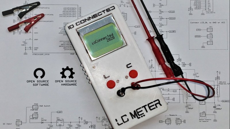
[core weaver]’s design is all through-hole, so even just assembling one would be a great exercise for someone getting started in electronics. However, he didn’t just release a design, in a series of videos he goes through the theory of the device’s operation; explains the design of the circuit, firmware, and case; and shows you how to put it all together. For times when you need to measure a lot of parts (e.g. if you have to sort a bag of cheap capacitors looking for specific value), he’s even developed a desktop program to save you some trouble!
The finished meter looks incredible! If you want to build one for yourself, he’s put all of the files up on GitHub, and we highly recommend you check out his first video after the break. If you’d like to build yourself a 6.5-digit DMM to go with our LC Meter, consider this one which even has a home-built ADC.


I was hoping it was slope conversion so that it could be extended to be a low ESR meter as well.
Also D1 (1N4148 like 1N914) has Vr of about 100v. That seems a little low for a relay back EMF protection diode. I probably would have used a 1N4004 (Vr=400v) or a 1N4007 (Vr=1000v).
D1should have written D2Everybody is using 1N4148 in that position for decades. Vr doesnt matter much because the diode is used in conducting (Vf) direction. The whole concept of this diode to conduct flyback current.
Those freewheeling diodes do not need to be rated for high voltages as long as they are rated for the current passing through the coil of the relay. They”ll start conducting in the few nanseconds before the back EMF get high. A rectifier diode (your 1N40xx) is a far worse choice as it turn on much slower than a switching diode.
I was looking through my shop this morning for the “magic eye” capacitor checker I once had.
Oddly enough, I must have gotten rid of it years ago.
I do have a couple military LCR bridges (BECO) bought at auction 20 plus years ago, but have been unable to obtain instructions for them.
The Beco 250 manual is available at BAMA (boat anchor manual archive):
https://bama.edebris.com/manuals/beco/250/
Thank you!
While it isn’t the same model as mine, it looks like I’ll be able to use it to make the LCR’s work!
(Printing it out right now)
But how is this different from those that came before?
The idea is old,except before frequency counters were cheap and available, you really didn’t get.much accuracy without a lot of work.
I got curious last year because I’ve seen lots of these projects. But I can’t be bothered recreating the bibliography. They all used the lm311 for the oscillator, and other than date I don’t know the beginning.
There was an article or two about using the 311 oscillator with a frequency counter, making tye calculations separate. One using a Commodore 64 to measure the oscillator, and make the calculations. A pocket unit in Radio Electronics that used ROM to provide the results after counting the frequency. And of course the cheap LC meter boards of recent years. I still don’t know where the oscillator originated, it’s not quite what’s in the datasheet and app note for the lm311.
Since elsewhere I’ve seen some confusion, given frequency (via frequency counter, one hopes accurate) and accurate capacitance (bought off the shelf), the unknown of the coil can be derived. So you don’t need a really accurate coil, or a separate means of measuring it.
Why does it have to be different?
Those oscillator LC meters aren’t too good for large values of L or C as the frequency gets too low to get accurate reading. Would it oscillates for low Q – electrolytic cap with leakages?
The famous transistor tester on the other hand has the reverse problem of not being able to measure small values.
The average crystal would be around 100ppm, so frequency measurement should be good enough.
Cap could be +/- 5% to 10% depending on the type and you can find better ones if you know where to shop. i.e. a large maiil order elctronic suppliers, not those arduino supply places.
mouser is my go-to-source where you can specify the % in your listing… Not expensive in the end…
I remember an issue of Radio-Electronics had an article about converting a cheap calculator into a capacitor tester. It used the calculator`s clock to time the charging of the capacitor.
Only at the time it was printed, calculators were not all that cheap (LED or VFD)
I love these types of tool – innovative and useful.
What I’d like to see marketed though is a set of workshop test equipment based on a digital multimeter format (the display being LCD dot-matrix, colour) and offering, in separate packages, such functions as AF sig gen, RF sig gen, pulse gen, variable PSU, attenuator, DFM, sweep generator, etc etc. The main DMM-style rotary selector could be a rotary encoder with push-to-select function accessing all menus.
Using the same style case and a universal DC input (so you can attach any old laptop PSU) the case would also utilise common output probes/clips – via the original DMM sockets – to keep costs low.
A basic set of these instruments, using current Chinese-type manufacturing facilities, could provide a full workshop setup for a few $$ each instead of the usual $$$ (or $$$$).
Many such building blocks already exist but there is no common format so workshops tend to end up as a mishmash of instruments (nothing wrong in that) and there is a huge potential market of experimenters who take ‘years’ to gather a full set of such instruments.
Maybe, in time, the line-up could include a decent ‘scope, speccy analyser etc.
The various tools and modules are out there – I wish I had the time (left) to do this as a start-up. Anyone????
Euro rack modularity.
I agree this has been done before, but it is a good piece of equipment to build. This reminds me of the Almost All Digital Electronics Capacitance meter that was available as a kit. I remember building that years ago and using it for all sorts of projects. There is a memorial page to the creator here: http://www.morsex.com/aade/lcmeter.htm
Is this an ‘open’ project? See blob-type (exe and lib) files with no source.
The firmware source is definitely there. Doesn’t look like the PC application is, but eh, that’s not the interesting bit (and being C# it would decompile trivially.)
How this compares to that Atmega Transistor tester? (It is called “transistor tester” but can test pretty much anything)
Well, for one, this one doesn’t test transistors!
B^)
Harvie, you forgot the link!
https://github.com/mikrocontroller-net/transistortester
Highly recommended.
While there is a lot of good info in the videos, I haven’t seen a detailed explanation of the circuitry for the Colpitts oscillator itself. Looking at the schematic on GitHub, it appears that the circuit around the LM311 is not correct. I don’t see how the inductor can avoid having one end connected to ground through the relays. What am I missing?
In one mode L1 and C12 are in series. In the other mode L1 and C12 are in parallel to ground. The DC ground reference doesn’t matter because of C11. In both cases they are a tank circuit.
From a DC perspective R16 and R17 form a divider to center the wave mid rails. From an AC perspective R16 and R17 are in parallel (effective 50k). These with R18 set a positive gain and hence oscillation.
R19 and C10 form a low Q filter and sets the range of oscillation and provides some rejection of noise.
R11 is because he is using an open collector output comparitor rather than a op-amp.
Thank you for the very helpful explanation. I get it now!
I’m assuming you mean R21, not R11 in your last comment.
Yep R21 (1k). Just a typo.
Fantastic project just what I need, will be building some RF low pass filters and this will definitely be a welcome addition to my test equipment. Case printed off, and started to populate the PCB, will post some pictures when finished. Having some issues finding Reed SIL 7271-L 5V RELAY_2UMNA05WK 1000pF C-11.5X4.5 C_CAL 1000pF C-US050-045X075 C12 would you be so kind in suggesting where I can source these components or supply specs, I assume the C_CAL capacitor needs to be .5% tolerance or lower? Many thanks.
know this was posted some time ago.. but I too am struggling to locate those Relays.
Can you please provide me/us with alternative part numbers please
https://www.mouser.com/ProductDetail/Littelfuse/HE3621A0500?qs=X8LBAgEWIKIc9wEjZ29LbA%3D%3D
More on the relays, etc,:
https://www.mouser.com/ProductDetail/653-G6S-2-DC5
https://www.mouser.com/ProductDetail/75-KP1830210631 (2x; requires bend one leg)