Finding broken test gear and fixing it up to work again is a time-honored tradition among hackers. If you’re lucky, that eBay buy will end up being DOA because of a popped fuse or a few bad capacitors, and a little work with snips and a soldering iron will earn you a nice piece of test gear and bragging rights to boot.
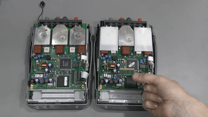
Some repairs, though, are in a class by themselves, like this memory module transplant for a digital scopemeter. The story began some time ago when [FeedbackLoop] picked up a small lot of broken Fluke 199C scopemeters from eBay. They were listed as “parts only”, which is never a good sign, and indeed the meters were in various states of disassembly and incompleteness.
The subject of the video below was missing several important bits, like a battery and a power connector, but most critically, its memory module. Luckily, the other meter had a good module, making reverse engineering possible. That effort started with liberating the two RAM chips and two flash chips, all of which were in BGA packages, from the PCB. From there each chip went into a memory programmer to read its image, which was then written to new chips. The chip-free board was duplicated — a non-trivial task for a six-layer PCB — and new ones ordered. After soldering on the programmed chips and a few passives, the module was plugged in, making the meter as good as new.
While we love them all, it’s clear that there are many camps of test gear collectors. You’ve got your Fluke fans, your H-P aficionados, the deep-pocketed Keithley crowd — but everyone loves Tektronix.


Wow, that’s amazing.
That memory module is so tiny, it has so many connections and so many layers.
It’s hard to contemplate reproducing that by hand.
A real undertaking, even if you do know what you’re doing, pretty impressive and a great result.
For me, it’s Rohde and Schwarz.
Reassuringly expensive, so when a CMU300 came up for £400, it was a baaaargin, Mrs Non-Robinson.
Holy cow….
Yeah, I would absolutely jump on that one too!
That is an impressive piece of equipment on any day with some impressive specifications to boot!
Somebody once told me that RS actually means “robust and schwer” (robust and heavy)…
A little bit beyond my capabilities but amazing
I like the videos of this guy. Sadly he did not tell how he reversed the PCB, just with a multimeter? He must have A LOT of patience… Good job!
Tried this a couple of times and though not on a comparable board, but either way, I can attest that it can be very tedious and confusing at times. Tracking every point of connection and plotting it to a schematic then retesting to make sure you haven’t missed anything, maybe more than a couple of times. Multilayer boards ? Can go either way on making routing easier or harder. And the traces for these are SO small. I noticed the boards were the same as each other and the chips are slightly different, so it was more than simply a process of plotting the original connection pads and then mapping out the traces. Each layer likely has some re routed traces from the original, it would be easy to get the top and bottom layers matched but 6 is another story, unless he was able to split them apart without damaging the runs.
I found a Tektronix TDS-3012B oscilloscope on eBay for less than the usual eBay price. I had used this model in work before I retired. Description said it was messed up. I turned it on when I got it and sure enough there was a red trace filling the screen with the normal green trace in the background. So I flipped through the soft keys and found the factory reset button. I did a reset and viola! I had a perfectly good scope for a great price!