Video De-shaker Software Measures Linear Rail Quality

Here’s an interesting experiment that attempts to measure the quality of a linear rail by using a form of visual odometry, accomplished by mounting a camera on the rail and analyzing the video with open-source software usually used to stabilize shaky video footage. No linear rail is perfect, and it should be possible to measure the degree of imperfection by recording video footage while the camera moves down the length of the rail, and analyzing the result. Imperfections in the rail should cause the video to sway a proportional amount, which would allow one to characterize the rail’s quality.

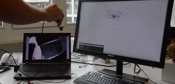
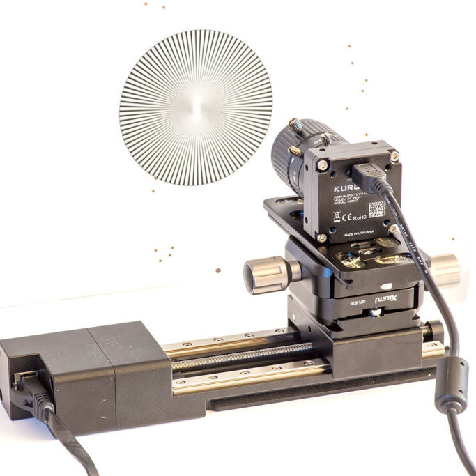
To test this idea, [Saulius] attached a high-definition camera to a linear rail, pointed the camera towards a high-contrast textured pattern (making the resulting video easier to analyze), and recorded video while moving the camera across the rail at a fixed speed. The resulting video gets fed into the Deshaker plugin for VirtualDub, of which the important part is the 
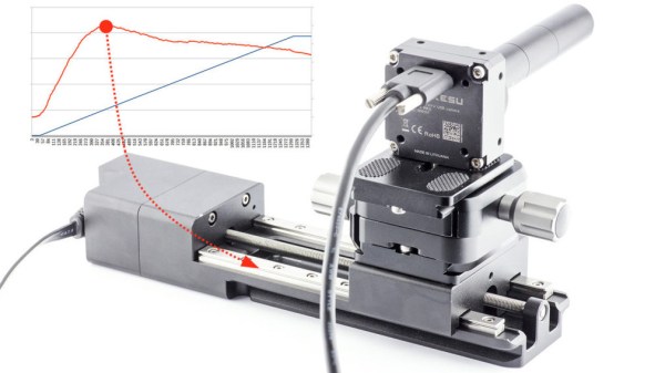
deshaker.log file, which contains X, Y, rotate, and zoom correction values required to stabilize the video. [Saulius] used these values to create a graph characterizing the linear rail’s quality.

It’s a clever proof of concept, especially in how it uses no special tools and leverages a video stabilizing algorithm in an unusual way. However, the results aren’t exactly easy to turn into concrete, real-world measurements. Turning image results into micrometers is a matter of counting pixels, and for this task video stabilizing is an imperfect tool, since the algorithm prioritizes visual results instead of absolute measurements. Still, it’s an interesting experiment, and perfectly capable of measuring rail quality in a relative sense. Can’t help but be a bit curious about how it would profile something like these cardboard CNC modules.

Turn By Turn Driving Directions From A Turntable

Many of us now carry a phone that can give us detailed directions from where we are to a destination of our choosing. This luxury became commonplace over the last decade plus, replacing the pen-and-paper solution of consulting a map to plan a trip and writing down steps along the way. During the trip we would have to manually keep track of which step we’re on, but wouldn’t it have been nice to have the car do that automatically? [Ars Technica] showed us that innovators were marketing solutions for automatic step by step driving directions in a car over a 100 years ago.

Systems like the Jones Live-Map obviously predated GPS satellites, so they used vehicle odometry. Given a starting point and a mechanical link to the drivetrain, these machines can calculate miles traversed and scroll to the corresponding place in the list of instructions. This is a concept that has been used in many different contexts since, including the “Next Bus in 7 Minutes” type of display at bus stops. Because a bus runs a fixed route, it is possible to determine location of a bus given its odometer reading transmitted over radio. This was useful before the days of cheap GPS receiver and cellular modems. But the odometry systems would go awry if a bus rerouted due to accidents or weather, and obviously the same would apply to those old school systems as well. Taking a detour or, as the article stated, even erratic driving would accumulate errors by the end of the trip.

The other shortcoming is that these systems predated text-to-speech, so reading the fine print on those wheels became a predecessor to today’s distracted driving problem. One of the patent diagrams explained the solution is to hand the device to a passenger to read. But if there’s a copilot available for reading, they can just as easily track the manual list of directions or use a map directly. The limited utility relative to complexity and cost is probably why those systems faded away. But the desire to solve the problem never faded, so every time new technology became available, someone would try again. Just as they did with a tape casette system in the 1970s and the computerized Etak in the 1980s.

[Photo by Seal Cove Auto Museum]

Using IMUs For Odometry

The future is autonomous robots. Whether that means electric cars with rebranded adaptive cruise control, or delivery robots that are actually just remote control cars, the robots of the future will need to decide how to move, where to move, and be capable of tracking their own movement. This is the problem of odometry, or how far a robot has traveled. There are many ways to solve this problem, but GPS isn’t really accurate enough and putting encoders on wheels doesn’t account for slipping. What’s really needed for robotic odometry is multiple sensors, and for that we have [Pablo] and [Alfonso]’s entry to the Hackaday Prize, the IMcorder.

The IMcorder is a simple device loaded up with an MPU9250 IMU module that has an integrated accelerometer, gyro, and compass. This is attached to an Arduino Pro Mini and a Bluetooth module that allows the IMcorder to communicate with a robot’s main computer to provide information about a robot’s orientation and acceleration. All of this is put together on a fantastically tiny PCB with a lithium battery, allowing this project to be integrated into any robotics project without much, if any, modification.

One interesting aspect of the IMcorders is that they can be used for robot kidnapping issues. This, apparently, is an issue when it comes to robots and other electronic detritus littering the sidewalks. Those electric scooters abandoned on the sidewalk in several cities contain some amazing components that are ripe for some great hardware hacking. Eventually, we’re going to see some news stories about people stealing scooters and delivery robots for their own personal use. Yes, it’s a cyberpunk’s dream, but the IMcorder can be used for a tiny bit of theft prevention. Pity that.

Insanely-Quick 3D Tracking With 1 Camera

Let’s face it: 3-dimensional odometry can be a computationally expensive problem often requiring expensive 3D cameras and optimized algorithms that can be difficult to wrap our head around. Nevertheless, researchers continue to push the bounds of visual odometry forward each year. This past year was no exception, as [Christian], [Matia], and [Davide] have tipped the scale in terms of speed with an algorithm that can track itself in 3D in real time.

In the video (after the break), the landmarks are sparse, the motion to track is relentlessly jagged, but SVO, or Semi-Fast Visual Odometry [PDF warning], keeps tracking its precision with remarkable consistency, making use of “high frequency texture” as a reference. Several other implementations require two cameras or a depth camera variant, but not SVO. It uses a single camera with a high frame rate between 55 and 300 frames per second. Best of all, the trio at the University of Zürich have made their codebase open source and available as a package for ROS.

Continue reading “Insanely-Quick 3D Tracking With 1 Camera”

Robotic Odometry From An Optical Mouse

One of the problems future engineers spend a lot of class time solving is the issue of odometry for robots. It’s actually kind of hard to tell how far a robot has traveled after applying power to its wheels, but [John] has a pretty nifty solution to this problem. He converted an optical mouse into an odometry sensor, making for a very easy way to tell how far a robot has traveled  regardless of wheels slipping or motors stalling.

The build began with a very old PS/2 optical mouse he had lying around. Inside this mouse was a MCS-12085 optical sensor connected to a small, useless microcontroller via a serial interface.

After dremeling the PCB and discarding the microcontroller, [John] was left with an optical sensor that recorded distance at a resolution of 1000dpi. It does this by passing a value from -128 to 127, rolling over every time the sensor moves more than 3.2 mm.

As far as detecting how far a robot has moved, [John] now has the basis for a very simple way to measure odometry without having to deal with wheels slipping or motors stalling. We can’t wait to see this operate inside a proper robot.