Hands On With The Raspberry Pi POE+ HAT

There’s a lot happening in the world of Pi. Just when we thought the Raspberry Pi Foundation were going to take a break, they announced a new PoE+ HAT (Hardware Attached on Top) for the Pi B3+ and Pi 4, and just as soon as preorders opened up I placed my order.

Now I know what you’re thinking, don’t we already have PoE HATs for the Pis that support it? Well yes, the Pi PoE HAT was released back in 2018, and while there were some problems with it, those issues got cleared up through a recall and minor redesign. Since then, we’ve all happily used those HATs to provide up to 2.5 amps at 5 volts to the Pi, with the caveat that the USB ports are limited to a combined 1.2 amps of current.
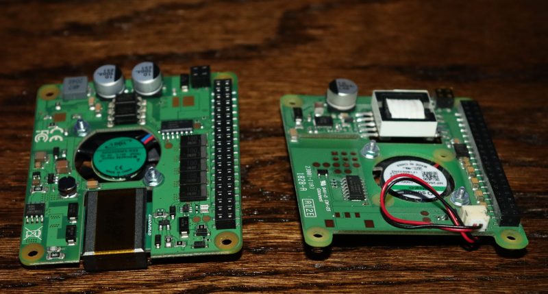
PoE vs PoE+
$20 for either of them. Choose wisely.

The Raspberry Pi 4 came along, and suddenly the board itself can pull over 7 watts at load. Combined with 6 watts of power for a hungry USB device or two, and we’ve exceeded the nominal 12.5 watt power budget. As a result, a handful of users that were trying to use the Pi 4 with POE were hitting power issues when powering something like dual SSD drives over USB. The obvious solution is to make the PoE HAT provide more power, but the original HAT was already at the limit of 802.3af PoE could provide, with a maximum power output of 12.95 watts.

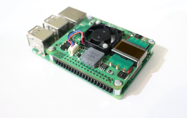
The solution the Raspberry Pi Foundation came up with was to produce a new product, the PoE+ HAT, and sell it along side the older HAT for the same $20. The common name for 802.3at is “PoE+”, which was designed specifically for higher power devices, maxing out at 30 watts. The PoE+ HAT is officially rated to output 20 watts of power, 5 volts at 4 amps. These are the output stats, so the efficiency numbers don’t count against your power budget, and neither does the built-in fan.

Continue reading “Hands On With The Raspberry Pi POE+ HAT”

Tetris Handheld Powered By Tritium Cell, Eventually

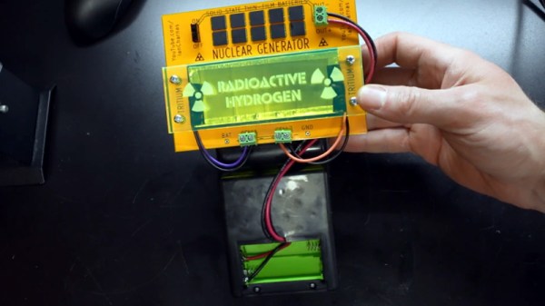
The idea of a tritium power cell is pretty straightforward: stick enough of the tiny glowing tubes to a photovoltaic panel and your DIY “nuclear battery” will generate energy for the next decade or so. Only problem is that the power produced, measured in a few microwatts, isn’t enough to do much with. But as [Ian Charnas] demonstrates in his latest video, you can eke some real-world use out of such a cell by storing up its power over a long enough period.

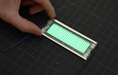
As with previous projects we’ve seen, [Ian] builds his cell by sandwiching an array of keychain-sized tritium tubes between two solar panels. Isolated from any outside light, power produced by the panels is the result of the weak green glow given off by the tube’s phosphorus coating as it gets bombarded with electrons. The panels are then used to charge a bank of thin-film solid state batteries, which are notable for their exceptionally low self-discharge rate.

Some quick math told [Ian] that a week of charging should build up enough of a charge to power a knock-off handheld Tetris game for about 10 minutes. Unfortunately, after waiting the prescribed amount of time, he got only a few seconds of runtime out of his hacked together power source.

His best guess is that he got a bad batch of thin-film batteries, but since he could no longer find the exact part number he used originally, he had to design a whole new PCB for the second attempt. After waiting two long months to switch the game on this time, he was able to play for nearly an hour before his homebrew nuclear energy source was depleted.

We wouldn’t consider this terribly practical from a gaming standpoint, but like the solar harvesting handheld game we covered last year, it’s an interesting demonstration of how even a minuscule amount of power can be put to work for intermittent applications. Here it’s a short bout of wonky Tetris, but the concept could just as easily be applied to an off-grid sensor.

Continue reading Tetris Handheld Powered By Tritium Cell, Eventually”

Fixing Noisy Measurements On An Owon XDM2041 Bench Multimeter

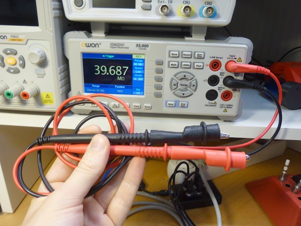
After purchasing an Owon XDM2041 bench multimeter for an automated test setup, [Petteri Aimonen] was disappointed to find that at especially the higher mega Ohm ranges, the measured values were jumping around a lot and generally very inaccurate. Since this is an approximately $170 bench multimeter and Owon support wasn’t cooperating, [Petteri] set out to fix the issue, starting with a solid teardown.

As noted by [Petteri], there’s not a whole lot inside one of these multimeters. The main board with the guts of the whole system contains a GigaDevices GD32F103CBT6 MCU coupled with the star of the show: the HYCON Technology Corporation’s HY3131 multimeter chip. After a peek at the HY3131 datasheet, the culprit was quite apparent: while sampling the presence of mains voltage noise is usually suppressed through the selection of an appropriate crystal.

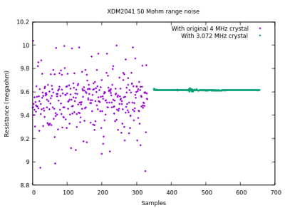
Unfortunately, instead of the recommended 4.9152 MHz crystal per the reference schematic for the HY3131, Owon’s engineers had apparently opted for a 4 MHz crystal instead, and so it’s essentially aliasing the line noise.

[Petteri] figured that the resulting sampling timing might work well enough with 60 Hz line frequency, but clearly with 50 Hz there was a lot of noise sneaking into the measurements. After swapping the crystal with a 3.072 MHz one, there was a marked improvement, as the plot shows.