Surface-mount technology has been a fantastic force multiplier for electronics in general and for hobbyists in particular. But sometimes you’ve got no choice but to use through-hole components, meaning that even if you can take advantage of SMDs for most of the design, you still might need to spend a little time with soldering iron in hand. Or not, if you’ve got a spare 3D printer lying around.
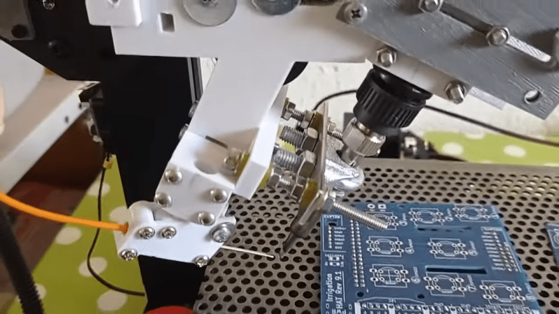
All we’ve got here is a fairly brief video from [hydrosys4], so there aren’t a lot of build details. But it’s pretty clear what’s going on here. Starting with what looks like a Longer LK4 printer, [hydrosys4] added a bracket to hold a soldering iron, and a guide for solder wire. The solder is handled by a more-or-less standard extruder, which feeds it into the joint once it’s heated by the iron. The secret sauce here is probably the fixturing, with 3D-printed jigs that hold the through-hole connectors in a pins-up orientation on the bed of the printer. With the PCB sitting on top of the connectors, it’s just a matter of teaching the X-Y-Z position of each joint, applying heat, and advancing the solder with the extruder.
The video below shows it in action at high speed; we slowed it down to 25% to get an idea of how it is in reality, and while it might not be fast, it’s precise and it doesn’t get tired. It may not have much application for one-off boards, but if you’re manufacturing small PCB runs, it’s a genius solution. We’ve seen similar solder bots before, but hats off to [hydrosys4] for keeping this one simple.
Thanks to [Arturo] for the tip!


> The video below shows it in action at high speed; we slowed it down to 25% to get an idea of how it is in reality
Video looks like it’s in realtime speed. Did you slow it when viewing, or what?
Otherwise – great idea. If that machine was used for more different boards, maybe he could create custom script to generate soldering gcode and models for jigs.
It says in the video “Sped up 6x” so, 15% playback speed would give you an indication of it’s true speed. The youtube player only gives you control down to 0.25x in the settings.
If you open the console in your browser (F12) and type in “document.querySelector(‘video’).playbackRate=.15” while on the youtube video page, it will play at 15%. This also allows you to play at higher speeds as well. My standard speed is currently 2.6x.
For maximum reliability, what you really want to “extrude” is molten solder, flowing upward like a fountain, with a cup to capture and recycle the excess. Add a 3-axis PCB vice to direct the solder flow, and you’d have yourself akin to a little “wave” soldering machine without the industrial size and fumes.
From what I’ve heard, those machines are much more fussy to operate right, they need constant monitoring to get flow and temperature right to operating conditions. Also constant flow of molten solder will mean that your solder will contain more and more oxides.
I have a selective soldering machine that does exactly this. The fountain sure is fussy, but the real problem is the flux. You can’t have flux-in-solder like with solder wire, it would just boil/burn out of a solder fountain. So, you have to have a separate flux nozzle and dispenser. On my used machine, the fluxer was damaged and non-functional. I’ve worked on replacing the valve for it a bit, but so far I haven’t found a reliable solution. So far, it’s been very difficult to apply just the correct amount of flux. The performance of the fountain (regarding tendency to bridge, etc) is dramatically affected by the flux.
The unit uses a shield of nitrogen gas around the fountain to help limit oxides… but that’s fussy as well, impossible to see for tweaks, and far from a complete shield. However, it’s at least pretty much ok.
All in all, this is all fixable… but as I was working the problems covid crushed my business down to 1/5 of what it was. I stopped working on the selective solder machine. I have one technician employee… he needs to stay busy or my wife starts bitching that I should lay him off. So, hand soldering it is.
Which is apparently called “fountain selective soldering”, and already done at fabs. It has the advantage of components on both sides of the PCB will still automated soldering of through hole components.
There’s usually some good selective soldering machine footage in the weekly Adafruit “Made in NYC” factory footage compilations. It’s fascinating to watch. Also cleaning the dross looks like such a Sisyphean task, more appearing as soon as you clear any.
Nate at Sparkfun posted a video to p&p group and it has one of these fountain machines in it. https://youtu.be/OyP3ulPGeZc
This discussion reminded me of the wave soldering machine we had at my first job. Amazing and beautiful to see it operate, but it was so difficult to use that it took a run of a few hundred boards to justify the setup effort by the costly tech staff. Any smaller job got hand-soldered by the cheap factory hands.
Should work for SMD components as well. Need a finer tipped iron of course. Perhaps a way to rotate the board and/or iron for the correct angle.
Or replacing the tool with one that blows hot air.
Looks like the springiness of the bed is important to getting a good firm contact between the iron tip and the components/traces.
I agree. It must have taken quite a bit of time to get this right and repeatable. I do wonder why solder paste wasn’t used. PIH, PIP, whatever acronym you care to use is a thing. Using a “printer” to meter out paste has been featured on HaD IIRC. Then it’s either a normal heating process or … use a frickin laser beam! That would be a hack!!
So, could you share a video with the whole board being soldered? Or with this template you can only solder headers?
Cool. I’ve visited PCB assembly houses in China where all the SMT assembly is automated (PnP etc.), but all through-hole assembly is done by hand using bench loads of women. Now they can replace all those women with modified 3D printers! Oh wait. Are modified 3D printers are more expensive than people in China?
If the video is six times actual speed, that soldering iron is sitting on the pin for 9-10 seconds. I wouldn’t want it doing an IC at that speed. Maybe need a hotter iron? Also, I wonder about oxidation on the iron’s tip. I clean my iron after every 1 or 2 joints.
So what I’m hearing is printing PCBs with conductive filament in one side of a dual extruder set up and regular filament in the other side.
I opted to get an old Apollo Seiko commercial soldering robot, as I figured that would easier to get working than a home built one. Here is some video of it in operation: https://www.youtube.com/watch?v=mLPmkOFfgTw&list=PLQ9LxBy2J29j7RbyPAukh1qzm6UrcYt8s
That is very cool, thanks for sharing! How much effort is it to set up a board?
It’s a bit of work, as a jig is required to hold the components and board in alignment. That’s probably the hardest part.
Programming can be a bit fiddly, but there is some software that sends most of the data to the machine from a computer. I crafted an Excel sheet that the pad coordinate data and sizes are entered into, and that generates the required data for the machine. It takes a bit of tweaking though, as the solder volume I calculate never seems to be correct.
Some things need to be programmed directly on the machine through the teaching pendant, but over all it’s not too bad. I’ve only run a couple of jobs at this point, but I’m getting better at it.
Well… actually you cannot see the video because I moved it to another youtube channel, my apologize to the author of the article. I’ve made more videos about this project as I implemented few modifications. If you are interested, here the link: https://www.youtube.com/watch?v=LzfXfgyOfFY&t=603s