Like many hackers, [Matthias Wandel] has a penchant for measuring the world around him, and quantifying the goings-on in his home is a bit of a hobby. And so when it came time to sense the current flowing in the wires of his house, he did what any of us would do: he built his own current sensing system.
What’s that you say? Any sane hacker would buy something like a Kill-a-Watt meter, or even perhaps use commercially available current transformers? Perhaps, but then one wouldn’t exactly be hacking, would one? [Matthias] opted to roll his own sensors for quite practical reasons: commercial meters don’t quite have the response time to catch the start-up spikes he was interested in seeing, and clamp-on current transformers require splitting the jacket on the nonmetallic cabling used in most residential wiring — doing so tends to run afoul of building codes. So his sensors were simply coils of wire shaped to fit the outside of the NM cable, with a bit of filtering to provide a cleaner signal in the high-noise environment of a lot of switch-mode power supplies.
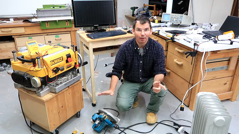
Fed through an ADC board into a Raspberry Pi, [Matthias]’ sensor system did a surprisingly good job of catching the start-up surge of some tools around the shop. That led to the entertaining “Circuit Breaker Challenge” part of the video below, wherein we learn just what it really takes to pop the breaker on a 15-Amp branch circuit. Spoiler alert: it’s a lot.
Speaking of staying safe with mains current, we’ve covered a little bit about how circuit protection works before. If you need a deeper dive into circuit breakers, we’ve got that too.
Thanks to tip-line stalwart [Baldpower] for the tip.


So many things wrong. You can’t re-write physics for your convenience. The field at some distance from the wires sums to zero. Positive current in one conductor, negative in the other. The magnetic field isn’t symmetric so you’ll get some un-cancelled flux very near one conductor but it will be extremely position-dependent and relatively low signal. A clamp-on meter which intercepts the total flux will read zero assuming there is no common-mode current. You actually do need to separate the wires so you can measure current in one wire using magnetic or inductive sensors.
There are a few multi-core meters that do exactly that: measure the near field of cables with known geometries. Megger had a couple of models and from what I’ve read the reading does vary so you move the cable and take the highest reading..
Bob, if you can find the time to watch the video you will see Matthias’ clear explanation of how it works.
I installed my current transformers in the back-boxes, behind the switches and sockets, since the cables are already split at that location. But you could do it the hard way if you like.
TI have some nice hall effect sensors that can be used for non-invasive current measurement. There’s even an application note for a complete meter.
Bit baffled by the notion of not being able to split live and neutral – they have to at some point in the consumer unit, surely?
They are split at the circuit breakers, and they are split at every outlet. The only advantage he can be getting is not having his sensors within electrical boxes. Which isn’t really an issue.
But even then, why does he have a problem with splitting the outer jacket on the Romex? Doesn’t make sense to me – if and when you ever remove it you can just wrap it with electrical tape.
I’d have a problem with splitting a layer of insulation on an extension cable – especially in a workshop, you just removed a huge amount of protection from the live conductors….
One of the better wood-working channels on Y/T. His approach makes much more sense than some of the mumbo jumbo emitted by the bazillions of channels of artistically-driven wood workers.
But do not understand his approach to measuring input inrush to determine breaker ratings. CBs are generally not intended to open during an turn-on in-rush. This is somewhat explained in IEC 62271-100, and circuitously (pun intended) talked about in ANSI C37.04 for the half-cycle operating time requirements.
So the pi and the external ADC are not gonna get it. Suggest a Teensy 3.5 (or better) with an decent 16-bit ADC that uses SPI.
Yes, circuit breakers won’t pop with a momentary current, even if that current is a couple of orders of magnitude more than they’re rated for (for half a cycle or so)… however, some things will go bang that fast, and those might require the power company do go digging. Definitely don’t know that from first-hand experience… 🤐
Sorry, not meant to be a reply.
The excess bandwidth of a GHz scope would come in handy here. Where in the half cycle the switch is closed has a huge effect on inrush – if the feeds can supply it.
Used to run all my wood working tools off a 50m 1.5 sqmm extension cable (240 V). The voltage sag was huge, causing them to take longer to spin up than when next to the house. Was more amusing when starting a planer with the dust collector already running. Never blew the 13A fuse.
The problem with the extension lead and the slow startup due to volt drop is way worse for things like lawn mowers which bog down frequently. So… This can be overcome by applying more volts to the feed end. Makes the mower run faster and tend to bog down less too. Only pushed it near 300V – feeding about 75m of flex. Hadn’t caught fire or flown apart, so clearly more headroom left.
As Bob already wrote in the first response here, the coil is positioned wrong.
The picture @01:55 is wrong to. Current runs in loops, so if the current is “coming out of” the paper on the left side, then it’s going “into the paper” on the right side.
Result is he should have drawn the circles clockwise on one side, and counterclockwise on the other side.
I am surprised why Mattias missed that. His hand wound coil works in the same way as the ferrite core of the current measurement transformer.
What he could (should?) have done, is to put one side of is coil as close as possible in between the two conductors to pick up more signal.
The current peaks are also completely realistic.
I once put a 1 Ohm shunt resistor in series with mains voltage to measure current with my scope, and I measured almost the complete mains peak voltage over that resistor during switching appliances on.
how did you deal with grounding (reference voltage) for the scope to measure across that 1ohm resistor?
I put both my scope and the devise under test on the same extension cord, and then measured which of the live wires is the phase, and which is the neutral.
Then I put the resistor in the GND wire of the 230Vac.
I did not use the GND connection of the scope probe at all, but instead relied on the connection between “Earth” and the “zero” of the mains wiring.
Normally I use an isolation transformer, but it was my 750VA toroidal isolation transformer that I was measuring.
During turn-on if often gives a audible “Poenk” noise, and a diminishing hum for a few seconds, and now I know why. The core goes heavily into saturation durning switchig events and it needs about 2 seconds to even out.
I did not attempt to measure the actual current, just that the voltage over the 1Ohm resistor combined with the mains wiring had almost the full mains voltage over it, and thus it could not be used to measure the current peaks of the transformer, as it had too much influence, but > 100A and only limited by DC resistance is very plausible to me.
Just take a big angle grinder and turn it on. A significant shock and it reaches 20.000RPM nearly instantly. That is a huge power surge. (180mm disks rotate slower, but i’s about a 3:1 transmission in those things)
An old trick for a simple measurement adapter is to use an extension cord, and then mark one wire as “GND” and the other as “phase” and add two neon bulbs between the “Earth” and those two wires. A green bulb, and a red bulb, and when the red bulbs lights, you turn the plug around. When the green bulb lights, you know where the phase wire is.
230Vac plugs are not polarized in Europe, and for normal consumers both AC wires are considered “live”.
These days, plenty of DMM’s have a “voltage sense” capability.
You can also use this to find the phase. Just hold the DMM in your hand, and put one of the probes in the mains socket. (the other is not needed) If it’s the phase, then the non contact voltage triggers, if it’s the GND wire, there is no voltage difference between your hand and the DMM and the non contact circuitry does not trigger. This works reliably on my Meterman 35XP. It does not matter much in which of the 4 sockets that wire is.
“The picture @01:55 is wrong to[sic]. Current runs in loops, so if the current is “coming out of” the paper on the left side, then it’s going “into the paper” on the right side.
Result is he should have drawn the circles clockwise on one side, and counterclockwise on the other side.”
That’s correct, and exactly what is drawn in the figure: they are clockwise on the right conductor, counterclockwise on the left, with the summed net magnetic field running vertically between the current-carrying conductors. And cancelling at a distance.
Plug the numbers into the Biot-Savart or Ampere’s law and you’ll see the magnetic field in the plane of the loop is about 0.1 mT per ampere, greater than Earth’s magnetic field; readily detectable.
Putting the coil vertically “in between the two conductors ” will intersect no magnetic field lines and will yield zero signal.
Oops. brainfart on my side.
Form of Mathieas’ coil looks quite reasonable, as an attempt to catch as much as possible of the field between the wires, and as less as possible of the field surrounding the wires.
But still.
For a (semi) permanent installation, you want to put such a device in it’s own box, or build it into an extentsion cord. And then there is no reason to keep the mains wiring intact an you can easily use a current tansformer on a single conductor.
“What’s that you say? Any sane hacker would buy something like a Kill-a-Watt meter, or even perhaps use commercially available current transformers? Perhaps, but then one wouldn’t exactly be hacking, would one?”
There’s always the…what comes after. Plenty of figuring what everything is doing on the network.
I’m 54% interested in current measurement but on a smaller scale than mains power. After watching one of Curious Marc’s videos from a few months back in which he used a Hewlett Packard 547A Current Tracer probe on some vintage computer boards, I went to the usual place like everyone else only to find these vintage tools are quite rare and listed at 600 USD.
Some other comments I found about making a repro probe mentioned a particular chip but that was about the extent of it.
Ok so 15A breakers pop at 135A, nice overrating.
15A is the continuous current rating. The purpose of a 15A breaker is to protect WIRING that can handle 15A continuously. Such current does not burn down your house, or even damage the wiring if you put 20A through it for a minute. Nor does it burn down your house or damage the wiring if you put 100A through it for a couple of seconds. They are specifically designed with mechanical or thermal delay devices to prevent nuisance tripping – tripping on loads that present no threat to wiring rated for their rated current. Most circuit breakers have two separate trip mechanisms, one that that handles overloads, which has the delay device, and another that trips within a half cycle on short circuits, which was probably what we saw trip in the video.
Wandel shows more confidence than I would in the breakers in his house, but he does understand that this is how circuit breakers operate, and did pull the plug after just a few seconds.