For prototype electronics projects, most of us have a pile of resistors of various values stored somewhere on our tool bench. There are different methods of organizing them for easy access and identification, but for true efficiency a resistance substitution box can be used on the breadboard to quickly change resistance values at a single point in a circuit. Until now it seemed this would be the pinnacle of quickly selecting differently-sized resistors, but thanks to this programmable resistor bank there’s an even better option available now.
Unlike a traditional substitution box or decade box, which uses switches or dials to select different valued resistors across a set of terminals, this one is programmable and uses a series of sealed relays instead. That’s not where the features stop, though. It also comes equipped with internal calibration circuitry which take into account the resistance of the relay contacts and internal wiring to provide a very precise resistance value across its terminals. It’s also able to be calibrated manually to account for temperature or other factors.
For an often-overlooked piece of test equipment, this one surely fits the bill of something we didn’t know we needed until now. Even though digital resistor substitution boxes are things we have featured in the past, the connectivity and calibration capabilities of this one make it intriguing.


Oh well, I already have a nice Chinese digital component tester that is quite useful, but always discharged when I want to use it.
Now I can add a resistor box to that class of tools.
Well, it is then the same as with your mobile phone – when you need it it is discharged, and you want to drive away and no petrol. There are ways to deal with those …
There’s a certain point to owning non-powered hand tools, such as an eggbeater drill. When you use them infrequently enough, all your battery powered hand tools will be empty and their batteries will be ruined by sitting empty on the shelf.
> and you want to drive away and no petrol
With electric cars, you can easily get into that situation. Quick googling around shows that a Nissan Leaf loses about 6 miles of charge sitting for a week. There’s something in the car consuming 10-15 Watts constantly when it’s turned off. There are also multiple cases of Teslas getting bricked by the owner leaving them in storage for a month of two and returning to a car that refuses to charge.
You really must not use your power tools very often then, lithium batteries tend to self discharge at MOST 5% per month. So even if you left it at 50% that’s probably a minimum of 10 months in storage for it to be dead. Even if the self discharge is higher than 5% due to the bms using power or something, you would still need to leave the tool in storage for a long time for it to be completely dead. A lot of people use their tools more often than that so it’s never really a problem. If you really don’t use your tools that often then why not get ones that can all use the same battery, that way if you leave it too long and the battery dies, you’ve only lost one or two batteries, also it means you only have one or two batteries to maintain and keep within an acceptable level of charge, so even putting in the minimum effort to keep your tools operational should be enough to charge one or two batteries every 6+ months.
I don’t know what range a Leaf has, but 6 miles / week? No problemo! Our car sits around half-full at 250 km = 26 weeks to empty.
Teslas have even bigger batteries, but they do a lot of active climate management stuff. (I was going to type “nonsense”, but they have extraordinarily good battery managment, so I’ll hold my tongue.) But yeah. If it’s too hot, the car turns on the AC for the batteries. Which drains the batteries, and will, I guess, ironically kill the batteries. Lots of Tesla owners leave their cars plugged in b/c of the passive consumption.
Fix it in software. :)
I wonder what happens when, not if, tyw intemal lithium cell dies
… this is HAD, obviously you replace the dead cells with new ones
To see is to believe, we engineers should talk based on test results.
Engineers talk based on predictions, which are then verified by testing.
The most a test can show is that in one specific case you weren’t unlucky.
“You can’t test quality into a product”.
Clint says:
July 20, 2022 at 2:32 am
To see is to believe, we engineers should talk based on test results.
Vintage laboratory resistance standards are traditionally cylindrical in shape [1][2], that is because the standard resistor element is immersed in oil to provide electrical isolation and thermal stability. The oil-filled cylinder containing the resistor is usually mounted inside a partially air-gapped outer cylinder to provide thermal isolation from the surface the standard is resting on.
This new programmable resistance standard is either intentionally or coincidentally also cylindrical, maybe to look like a vintage lab standard resistor. I so, I like it.
But I see some issues too:
(a) There is a two-wire measurement connection. Instead it should have at a minimum a four-terminal connection to allow “Kelvin Sensing”.[3]
(b) While the resistance standard is specified to be electrically isolated there is no statement that it is electrically shielded, in-fact there is no ground connection at all – which should bring the total number of external measurement connections to five.
(c) I see no serious effort to thermally isolate and/or stabilize the resistance standard. There are actually powered electronics inside the standard’s enclosure, That sets alarm bells off in my mind!
Other than that, the programmable standard is beautifully built. However, for casual use I would probably buy or better-yet build a stand-alone passive precision resistor substitution box.
* References:
1. Guildline Instruments 7330 Series of Oil Based Resistance Standards
https://guildline.com/primary-electrical-metrology/resistance-standards/oil-based-resistors
2. 1Ohm-100kOhm 0.01% Resistor Standard Resistance an-g of L&N, ESI, iet, GenRad US $89.73 ea. (used vintage)
https://www.ebay.com/itm/232061130319?hash=item3607ebd64f:g:-98AAOSwz35bFnaM
3. Four-terminal sensing (a.k.a. Kelvin sensing)
https://en.wikipedia.org/wiki/Four-terminal_sensing
(b) While the resistance standard is specified to be electrically isolated there is no statement that it is electrically shielded, in-fact there is no ground connection at all – which should bring the total number of external measurement connections to five.
CORRECTION
There IS a small ground connection, I missed it. Sry :-/
Nice one. 1 Ω ~ 1.2 MΩ range is decent, and 1W rated power should cover many applications.
If one just needs a lower resolution, lower precision and lower power variable resistor, it´s also possible and way cheaper to use an I2C or SPI potentiometer.
Most are 8 bits resolution only (256 steps) but some reach 12 bits. It´s also possible to increase the resolution with some tricks:
https://www.analog.com/media/en/technical-documentation/application-notes/an-582.pdf
You have to be a little careful. Like Humpty Dumpty they are using terminology in different way to other manufacturers.
For example, their comparison with other devices states “Residual 0ohms” for their QR-10, and “Residual <0.39ohms for the ITELabs RS-201".
However, that's a misleading comparison, since the QR-10's minimum resistance is 1ohm, not <0.39ohms. Make sure you understand what they mean and don't mean by "residual".
In addition, it may be worth assessing their "thermoelectric potential (EMF)" specification to understand whether it would be important in your application.
All tools have limitations; manufacturers should open and explicit, and users should assess tools vs specific applications
Hi, they just updated their FAQ and explained:
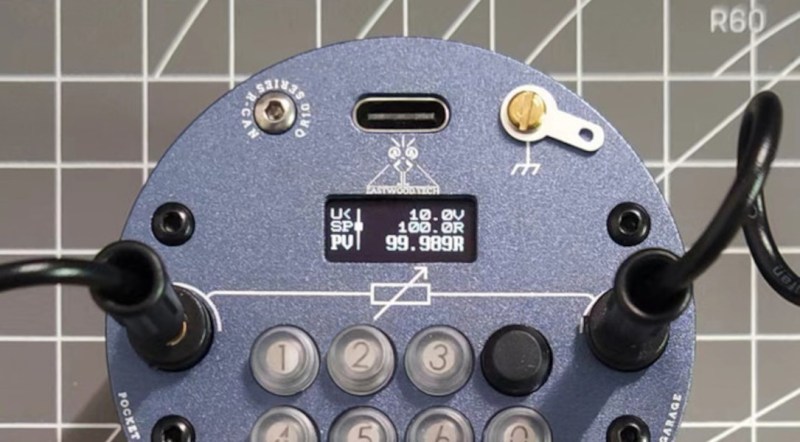
“if PV says it’s 1.000 Ω output which means IT IS 1.000 Ω OUTPUT. Socalled “residual resistance” already included in PV.”
So do we have to know “residual resistance”?
Whether you need to know the residual resistance is not a useful question.
You should use words in a way that is understood by others. If you don’t then – at best – you are making language irrelevant.
Usually that means continuing with accepted meanings, not changing meaning to something that is convenient for you. Using “residual” in the way the kickstarter page does (?did?) fails that test.
Their other terminology is strange too. Why have a “Process Value” in a resistance box? That terminology has, for some unknown reason been borrowed from completely different fields.
Hi, you must be tggzzz from EEVBLOG. I’m impressed by your argument but just don’t understand why you refused the challenge from Tigerwoods? I have plenty of excellent devices for you and they all free to use.
Nice, for DC & LF work, but I suspect if little use for fast analogue / RF work. Small multi turn low value (200R) cermet pots work fairy well for that, up to a few 10’s of MHz at least..
Don’t they know? Resistance is futile.
Yet another overcomplicated solution to a simple problem I will stick with my decade boxes they reliable no software silliness
Sure for what you do, but I can imagine a scenario where I want to run a characterization of a DUT by changing some resistance and logging the output over a wide range and automating a programmable solution like this is way better than sitting there or paying someone else to manually fiddle with switches. I just don’t get comments like this that only consider their own situation and come to a blanket generalization that something must be useless just because the commenter’s scope is rigidly outside the use case to begin with and thus no one outside that scope could ever possibly have a use for it too.
You´re a real man. For that same reason I´m sticking to my horse buggy, no overcomplicated engine or ciculation rules and maintenance schedule, and no parking fees.
Sure I´ll never ride on a highway, but what for ? I just transporting menhirs from the quarry to the Tesla gigafactory..
I’ve been thinking about similar lines, but a bit higher power. something like 0.01Ohm to 1kOhm but with a capability of several amps. Mechanical construction of each decade would be a circle of brass (M3 or M4) bolts around a stepper motor. The goal is to create a variable resistor / load that can be used for both AC and DC testing. But I do not have enough use for such a project myself to actually build it. Currently I do have a few power resistors. My 10 Ohm 25W resistor is one of the most used for testing. A bunch of power resistors with (banana?) connectors is probably the best compromise between price ans usefulness.
Stepper motor and one of those giant wire-wound pots?
Should work just fine. Watch out at high frequencies, though.
Read the comment before posting! He never wrote about a big coil, he wrote about an ARC of thick brass, that is not a coil
Might I add the Saturday afternoon with your kids do it yourself build idea:
Decimal thumbwheel switches with lots of resistors (about ten-1 for each decade). Easy to build and gives a nice bang for bucks ratio.
Seen on https://hackaday.com/2012/08/21/building-a-resistor-substitution-decade-box/ already.
HerkyDerk special programmable resistor… ORP12 with a PWM powered LED wrapped to it with black tape.
A transistor socket with a nearby tray of 1% resistors in labeled bins would be simpler, almost as fast to use, actually work for RF applications, and better simulate the finished product. This project looks to me like complexity for the sake of complexity.
… so rote manual labor is a plus for your applications? … well good I guess, but there are applications outside of your imagination where this level of automation would be a time saver.
It is added complexity for the benefit of automation capabilities
tggzzz wrote:
“I don’t have any sufficiently good equipment that is still within calibration, so I could only annoy you and embarrass myself.”
“Why do you want to see results from out-of-calibration equipment?
What value would it add to your claims and/or your device?”
and,after repeating that question there was a strange response, one of several in that thread.
That’s some impressive work. I certainly could’ve used such a device this past weekend, when trying to set the overcurrent trip point on an old Associated Research 2850 megohmeter. It uses a resistor, about 10-20 kΩ, in parallel with a neon panel lamp to limit output current, and indicate overload. I love the simplicity (and yes, dangers) of some 1960s electronics. LoL
A classic way of destroying a resistor box is, of course, to use it where current is not limited. That can burn out the relevant resistor, usually the lowest valued one.
The OR10 is compared with conventional resistance boxes where what happens while changing the set resistance is both simple and predictable..
It is unclear whether the QR10’s relays would chatter during switching, and whether there is any guarantee whether the transient resistance could be very high or very low compared with the set value. That might cause problems in applications similar to yours. For example, a transient low resistance might damage resistors or relay contacts, or a transient open circuit might damage your external circuit.
All tools have non-ideal behaviour, and it is useful to know how they affect individual applications.