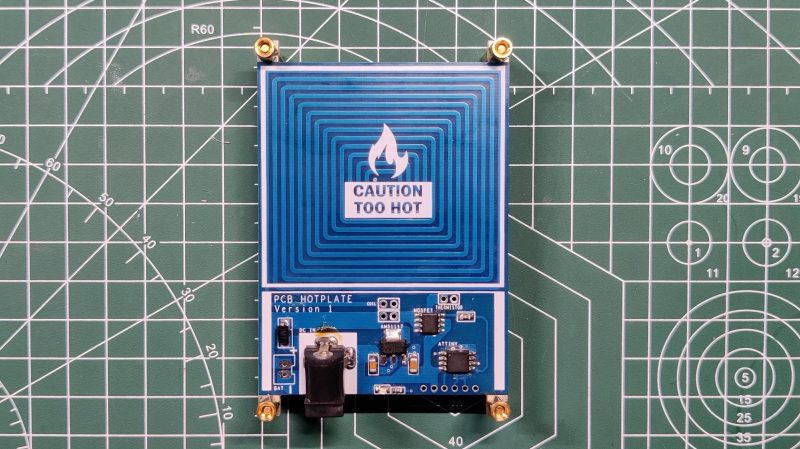
Normally when we talk about PCBs and hotplates, we’re talking about reflowing solder. In this build from [Arnov Sharma], though, the PCB itself is the hotplate!
The idea was to create a compact hotplate for easily reflowing small PCBs. To achieve that, [Arnov] designed a board with a thick coil trace that acts as a heating element. The full coil trace has a resistance of 1.9 ohms, and passing electricity through it generates plenty of heat. Running off a 12 volt supply, the mini hotplate is capable of reaching a maximum temperature of 214°C. Higher voltages can push that figure higher.
The board is intended to self-regulate, with an ATtiny13 onboard and a thermistor to measure temperature. However, in the initial design, this feature didn’t quite work properly. Version 2 is intended to include a better temperature sensor and a OLED screen for displaying the current temperature to the user.
We’ve seen other tiny hotplate builds before, too. They’re great for smaller projects and for hacking on the go! Video after the break.


Kind of ironic to use a hotplate to reflow a hotplate PCB. Now if you could make the PCB reflow its own components in some clever way… bootstrap reflower? Who wants to make it first?
You could make one side the heating element and place the components on the other side.
Bonus points if your turn the former heating traces into a receiving coil for inductive charging.
Continuing along this line of thought…
You have two heating elements, the normal one and the bootstrap one underneath the components. The bootstrap element plugs directly into 120VAC with prongs included as part of the PCB. Once you’ve reflowed your first unit with the bootstrap method, you use it to reflow the others.
(/s?)
Love this… It needs to be done
If the hotplate is made on an aluminum core PCB, then it is quite possible, as the heat would transfer to the components. A breakaway slot would then prevent the heating element from desoldering the components, and appropriately-sized wire would connect the element to the controller. Standoffs can be used to limit heat transfer.
Maybe a dedicated coil under components only for reflowing the components designed to be connected right to the power supply. And then a different coil for other boards.
Very nice! But at those temperatures I suspect it won’t be too long before the heater portion starts to delaminate. I’d be tempted to make two separate boards, with the driver as a keeper and the heater as a throwaway part.
I’m wondering about using a metalcore board for this. You can get high temp, high TG copper-clad with eg polyimide core material that’s good up to 220C, and higher yet for ceramics, but just going straight to aluminum with polyimide/copper in a single layer on one surface seems pretty tempting.
Not sure if that’s an issue at reflow temperatures. I reuse the same PCB as stand-off in my reflow oven for years without visible damage except for the browned silk screen.
As for this project, I would add a big cut-out to contain most of the heat within the desired area.
Check Carl Bugejas hot plate builds. Allot of information there.
I always wondered how many amps were needed to create a PCB 3D-Printer hotplate. Ideally a 4-layer board. Inner 1-2 will heat, outer one will be directly printed on. On the bottom side, you can directly mount a thermistor or two.
But price increases significantly with size. 10×10 (cm) is dirt cheap. 25×25 is still reasonable, but if you want an Ender3 35×35 PCB, you’re looking at >25$ per board in low quantities (or half that for 1000)
Add thermistor, solid sate AC relay and Arduino for PID control to this if you care about maintaining a reflow temperature profile. I think I’ve seen that exact project somewhere, but can’t find it right now. Anyone got a link?
300W PTC Heating-Soldering Plate – Hot Plate LED Remover Chip Welding Station for LED Repair DIY Laboratory – 120x70mm / 4.72”x2.76″ – US$13.99 shipped
https://www.amazon.com/dp/B07W1ZZH8T
From a review:
“It heats up at about 2C-3C per second, which is perfect, and reaches 230C, as measured by a k-type thermocouple affixed to the top of the plate with some Kapton tape.”
This was one I build a few months back – https://www.hackster.io/john-bradnam/smd-reflow-hot-plate-64969a