[PWalsh] was using his lasercutter to cut acrylic, expecting the cuts to have a pleasantly smooth edge. Alas, the edges turned out to be wobbly and sandpaper-like, not smooth in the slightnest. Bummer! Internet suggested a stepper motor swap, but not much in the way of insights – and that would’ve been a royal pain for sure. How would you approach debugging such a problem? Well, [PWalsh] didn’t want to swap crucial components willy-nilly, going the scientific way instead, and breaks it down for us.
Having compiled an extensive list of possible places to look for a fault in, he started going through fundamental assumptions. Do other lasercutters experience this issue? No, even the cheap ones can cut things properly. Is it water level causing intermittent cooling? Nope, not that. Is it the stepping settings? Tweaked, not that. Laser pulsing frequency? No dice.
 Air assist? Yes! Somehow, air assist was causing the jagged edges, and merely unplugging it turned the cut edge into a smooth surface. Running assist-less is not the way, and further debugging was done. Is it the power supply or is it the uneven flow of air, causing “puffs”? An air tank was added inline with the assist tube, smoothing out the flow, and the issue disappeared for good. Bonus points – going through steps debugging the issue, the cutter also got some much-needed maintenance checks.
Anyone who’s even debugged a bizarre issue with a 3D printer, can relate to such an experience, and could perhaps appreciate a bit of scientific approach to the problem. After all, 3D printing itself can be a bit of a science you get into with your printer’s purchase, and problems can spring up where you don’t expect them. Debugging stories are always fun to learn from, and having the right mindset from the get-go will help you save plenty of time you could spend printing or cutting instead.


So, how does uneven air flow cause wobble?
I am ignorant of the workings of a laser cutter.
Project author here.
The beam passes through mirrors and down through a lens to focus on a spot at the surface of the material.
As the material is cut, burned and molten material is cast off in many directions and smoke is produced. If the smoke wafts up into the lens it can stain it, and if a blob of molten material jumps up and sticks to the lens, the laser will burn it and make a burned spot on the lens.
To prevent this, the tube holding the lens is fitted with an air hose to gently blow air down through the tube (below the lens) and onto the cutting focus. Smoke and cast-off is blown away by the action of the air through the tube, and the laser beam is unaffected by the air.
“Puffing” air through the laser nozzle causes the ragged edge effect.
I was thinking about this, and was wondering if the puffs of air had an effect on the index of refraction of the air, but a pressure differential of even 5 PSI has a negligible effect on index of refraction.
The puffing could trigger an opposite momentum – essentially causing the laser head to jump up in response to air spewing out, but the differential amount of momentum is negligible.
Maybe it has something to do with heat conduction, the higher pressure burst causing heat to diffuse more rapidly than the low pressure burst.
I didn’t pursue the actual reason (my goal was to simply fix it), but if anyone has any ideas of why this happens, let me know.
Could it be that the lens assembly is not very rigid pushing the laser out of alignment as a function of pressure through the tube? Since it’s almost like a sinus or charge/discharge of a capacitor waveform it must be something cyclic.
Is it limited to any axes? Is the y axis worse compared to the x axis?
That’s similar to my guess. The air flow being irregular could also cause tiny thermal changes in the optical mechanism it’s trying to protect. Those changes could cause enough variance to make it change focal lengths causing jitter. This is something you can see on a larger scale with telescopes. Amateur scopes have to reach ambient outdoor temperature before they hold a fine focus.
I was thinking more along the lines that the air puffs were deflecting the lens holder given the consisdtency of the peaks and troughs of the wave.
> The puffing could trigger an opposite momentum – essentially causing the laser head to jump up in response to air spewing out, but the differential amount of momentum is negligible.
Not exacly releated to you, I read, like less than week ago, somebody make an air molecule sensor adaptor like x18 better but copying dog sniffing.
One thing is the dog is puffing (like 5-10 per second?, thought it was pushing air toward his back to drag air into his noise)
I wish I could find back the article :(
It was shown in one of the latest Veritassium’s video, very cool science in that video!!
Just a guess, could the air cause a harmonic vibration in the mirror assembly, and this would cause the wobble.
My bet is that the hose was flexing slightly. As the pressure changes it can act on the entire inner surface of the hose. This would induce flexing or torque. Is not much force but the hose is a force multiplier and it wouldn’t take much flexing to shift the head where the air is introduced to the mirror assembly.
I’ve seen similar issues with wobble and have found that if the laser lense was not tight, it had a tendency to wobble during fast turns and possible changes in air pressure from the air assist. Something to think about.
Someone beat you to the punch by 10 minutes.
The lens retaining ring had worked its way down the tube (more than 10 turns loose), so that the lens was sitting loosely on the ring. Puffs of air cause the lens to jump up, changing the focus and cut width.
The retaining ring on my cheap chinese laser cutter comes with no plastic washer – the metal presses directly against the (fragile) lens.
That’s probably the source and solution to the problem.
The lines were from pulsating air flow from a particular kind of pump. Probably a diaphragm type. A tank adds a bit of buffer and “shock absorption” and evens out the flow.
Same idea, my grandfather, who bred Angel Fish always suggested adding a large soda bottle inline with the aquarium air pumps to lower the noise and stress on the fish.
it’s an airpacitor.
I wonder if that’s why my goldfish died after I put an airstone in.
This is a classic shorthand example of process problem solving, skipping the flowcharts/correlation studies/Ishikawa diagrams etc. (as well as the six-sigma nonsense, thankfully). What often gets overlooked once the fundamental cause (intermittent misalignment of the lens by pneumatic surges) is exploiting the problem for other uses, or “It used to be a bug, but now it’s a feature”. What if you *wanted* the textured surface on the edge of the cut piece for some reason? Could you make the texture more regular? Can you vary it predictably?
All of the methods that you listed are needed in organizations when non-engineers are the ones writing the checks for the repairs.Or even for some that need to organize and document their process so it is duplicable. It is not simply enough to trust someone you are paying at their word that a fix is the fix. So “non-sense” is a bit misdirected here, especially since they have a place.
that, and decreasing the bus factor when it comes to doing maintenance on a piece of technology – it’s good when the next engineer to come fix something, has proper documentation on what went wrong last time, and can get a glimpse of the reasoning used in previous attempts! all in all, a myriad of reasons of why equipment owner would want to have documentation on previous repairs.
Nothing new here. Pulsations caused by pump/compressor or flow induced pulsations (think vortex shedding) are a common issue to be considered when designing a hydraulic systems.
I know you said you found the solution to your problem, but what type of belts are used in your system? Do they happen to be GT2?
If capable should have used nitrogen gas, with air and oxygen the fumes burn. Yes I have cut lexan and plexiglass with a 2000 watt laser.
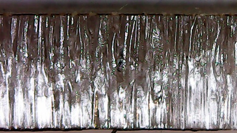
If your air pump was puffing that much, then it may have had an influence on the amount of smoke in the laser beam, and thus on the amount of light absorbed or reflected by the light, and the amount of laser light that hits your material is not constant.
When I look at your photograph (with the lots of laser lines). I do not see deflection of the slot, but changes in width, which is another indication that the amount of power reaching the material may be changing.
The picture above it (your reference) does have a constant width, but at some places it’s not straight either. That looks more like a bit of vibration or deflection.
Nice
I had a similar issue with my Chinese laser (K40) and found that it was the vibrations from the air pump used for the air assist that was causing the rough edges on my acrylic cuts. When I turned off the air assist the edges were much smoother. Originally I had my pump mounted inside the chassis, but when I moved it outside of the laser and onto the floor, I was able to use air assist and still get clean lines when cutting acrylic.