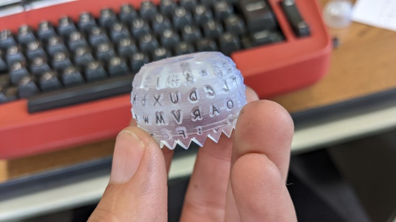
IBM’s Selectric line of typewriters were quite popular in the 1960s, thanks in part to an innovation called the typeball which allowed for easy font changes on a single machine. Unfortunately, as if often the case when specialized components are involved, it’s an idea that hasn’t aged particularly well. The Selectric typewriters are now around 60 years old and since IBM isn’t making replacement parts, those restoring these machines have had to get somewhat creative like using a 3D printer to build new typeballs.
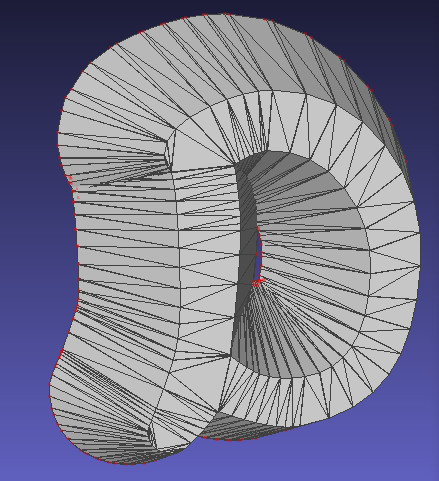 It sounds like it would be a simple, but much like the frustration caused with modern printers, interfacing automated computer systems with real-world objects like paper and ink is not often as straightforward as we would like. The main problem is getting sharp edges on the printed characters which is easy enough with metal but takes some more finesse with a printed plastic surface. For the print, each character is modelled in OpenSCAD and then an automated process generates the 3D support structure that connects the character to the typeball.
This process was easier for certain characters but got more complicated for characters with interior sections or which had a lot of sharp angles and corners. Testing the new part shows promise, although the plastic components will likely not last as long as their metal counterparts. Still, it’s better than nothing.
Regular Hackaday readers may recall that the ability to 3D print replacement Selectric typeballs has been on the community’s mind for years. When we last covered the concept in 2020 we reasoned that producing them on resin printers might be a viable option, and in the end, that does indeed seem to have been the missing element. In fact, this design is based on that same one we covered previously — it’s just taken this long for desktop resin 3D printing technology to mature enough.


Actually the original ones I have seem to be made from metalized plastic. The coating is not that thick to keep them light enough as the acceleration they endure during typing is quite high.
Nickel or chrome are fairly hard, seems like a good strategy.
This looks like a possible application for electroforming. Resin-print a negative of the required ball, then electroplate metal (probably Nickel) inside that.
It was a popular way to make memorial plaques and other complex, thin, one-off metal parts in Victorian times: https://en.wikipedia.org/wiki/Electroforming
There is an Instructable on the subject here: https://www.instructables.com/Copper-Electroforming-on-3d-Printed-PLAABS-Objects/
This seems like a good candidate for lost wax (burnable resin) casting.
Agreed. Can’t even imagine trying to squirt one of these out on an fdm printer…
I did the original project this is based off. At the time I only had a 0.4mm nozzle so the results weren’t great. I now have 0.3, 0.2 and 0.1mm nozzles but haven’t revisited the project to try them (too many others each wanting their timeslice lol).
I don’t think cast metal is the way to go, its going to be heavy compared to plastic and if it worked then IBM would have used that instead. Plating might be ok but these are limited use so there’s really no need to bother going to the extra effort.
Congratulations to Sam for persevering at getting the characters right!
>too many others each wanting their timeslice lol<
So True!!!
I finally broke down and started a mini-farm to deal with that. I print mold masters for slip-cast ceramics, and at 0.05mm resolution prints often exceed 4 days. Given that many of the molds are multi-part it can easily exceed a month for a single mold… However, used Prusa i3 MK3S+ printers are starting to show-up on eBay at almost affordable prices.
FWIW, a 0.05mm PLA print from a 0.4mm nozzle requires almost zero post processing and is smooth enough for making silicone or plaster of paris mold parts.
So, for now the main limits are creative inspritation and my limited Fusion 360 skills…
My family owned a ceramics business in the 70’s and 80’s, one of the largest suppliers of greenware and bisque in the Pacific Northwest. That was some fun stuff, especially the Slip-O-Matic we used to fill molds, and for the really large ones we’d use it to pump most of the slip back out. We had a huge pouring table with two stainless steel chutes that dropped into a stainless steel tank, with a hose to the Slip-O-Matic. The chutes were topped with grates made of wood so they wouldn’t damage the molds.
If you get bumps in the bottoms of items like vases, there’s a simple trick to eliminate them. When dumping the slip out, lay the mold on its side for a few seconds so the liquid slip runs off the bottom, then tip it upside down to finish draining. Many of our competitors just couldn’t figure that out, even after we explained it to them.
This is cool to hear. I’ve been printing forms for investment casting using 0.4/0.05 and have been frustrated by the surface texture and was going to get a dedicated machine for a 0.2 nozzle because swapping is a pain, but this gives me hope that maybe if I work on settings a bit more I can get it better.
I have some originals which I would like to sell or give away. will put on Ebay soon
Thank you for the writeup, Bryan! A few things to point out:
1) I will have a better version of the code up quite soon thanks to some valuable community input :D
2) The original Selectric typeballs are not metal! They are metallized plastic, and the metallization layer wears off eventually. I am curious how long these balls will last compared to the originals, but I think it should be pretty comparable; those Formlabs resins are tough. Speaking of which…
3) “it’s just taken this long for desktop resin 3D printing technology to mature enough” I don’t want to gloss over the fact that I’m extremely lucky to have ready access to a high-end Formlabs printer and fancy resins through my work. Whether or not this will work on a budget resin printer is something I still haven’t tested.
Also, if anyone in the LA area has a working Selectric I can test on, please let me know :) It’s tough finding one in fully working order!
The minkowski() operator scales with the product of the number of vertices in each child, so you want to minimize the number of vertices in each. Obviously any reduction in the extrusion for the letter shape comes at the cost of fidelity, but have you considered reducing $fn on the cone for the draft angle? I expect you could go as low as $fn=4 without making a practical difference.
You’re quite right–with the speed/fidelity tradeoffs, $fn=24 was the right choice for me personally, but ultimately it’s no less functional than $fn=12 or $fn=4. I’d lower it if I was doing a typeface with way more detail, like Papyrus or Jokerman. But I’m not sure I can justify making Papyrus or Jokerman typeballs!
My original motivation for printing typeballs was to replicate the 988 APL ball for an IO Selectric. I have an original 988 but its 2nd generation latch is slipping badly and in danger of breaking, so a repop was what I wanted. The 988 is a BCD ball, a friend has the 987 APL Correspondence version which would also be great to repop.
Steve, thank you again for pioneering this project. This would not have happened if it weren’t for your printed typeball! Is there any way I can help get you a new APL ball? It’s 88 characters, shouldn’t be too tricky, right? ….right?
Now up to embossed-tape font wheels (which should be comparetively easy)
Sounds like a fun project; what script/font would you like to see if I do a proof-of-concept? No promises, haha!
Do Eurostile so we can live in a world that has all the retro-futurey style of a spaceship from 2001 but the ghetto version where all the controls are just labeled with Dymo tape.
It’s interesting/frustrating that both selectric and dymo are strictly limited in the number of characters per printhead. It’d sure be cool to do kanji, but, ugh. (I just got a katakana/hiragana dymo, and it’s fun.)
With that said: runic, hieroglyphic, dingbats, the things we all played with when we first got word processors that had wide choices.
What about printing daisy wheel replacements?
I’ve never actually seen a daisy wheel IRL! It looks like it could be doable on an FDM machine, but I really don’t know enough to say.
The forces on them can be extreme. A Diablo 630 with a 15″ wide carriage was rated at 40 characters per second with a plastic type wheel. It could whip its heavy carriage the full width of the platen in a fraction of a second. A very sturdy table (preferably with a sound enclosure) was required. I had one connected to a Xerox 820 II.
Over 200 different type wheels were available in metal or plastic (metal wheels dropped the speed down to around 32 CPS but would last just short of forever) including IBM Extended Character Set ones with two characters per petal. They required an ECS capable printer that could shift the print mechanism up to hit the inner ring of characters. Monospaced and proportional wheels, even wheels made for printing graphics and vector plots were made.
Some Diablo printers had flat backs on the wheels and some had V ridges with a matching notch in the hammer to improve print alignment.
The first Diablo printer was made by a team at Singer. The manufacturer of sewing machines had no clue what do to with the project, so the printer team pulled up stakes, took their invention with them, and established Diablo printers, naming their invention the HyType, which they insisted was NOT short for Hyper Typer. The HyType II series followed, then the Diablo 630 series.
I think the main reason Selectric typeballs are more popular than daisywheels, is that there are too many kinds of daisywheels, while there were only ever two Selectric balls, 88- and 96-character. But while arranging typefaces on a sphere is a bit more complicated than on a disc, as for the quality of printer required, this does not depend on the shape of the type element, but on the expectations for the type itself. The first truly “letter quality” printers that didn’t use physical type, had at least 300 DPI of resolution, which translates into .003″ or 85 microns, which is a challenge either way.
Gotta make a few for mine… No, not Comic Sans. LOL
Problems with sharp corners etc will be due to using screen fonts rather than traditional print fonts, which had ink traps etc to resolve these issues.
Lost knowledge and all that…
I used these in school and they were old then, the ball was definitely aluminum and not plastic as I took it off and examined.
They definitely LOOKED aluminum. I tried modifying a typeball once, because I wanted to use it on my Anderson-Jacobson printing terminal, by replacing the 1/2 and 1/4 symbols with . When grinding off the original type, I found that there was around .001″ to .002″ of metal, but under that was hard plastic.
lmfao is that comic sans
Yeah, that’s the first thing I saw. When people ask “why DIY?”, THIS is the answer.