A 6502-based single-board computer with a ROMulator attached

Debug Your Senile Computers With The ROMulator

Some of you may have heard of the ROMulator, a device that can emulate RAM and ROM on 6502-based computers. But how does it work? How do you use it? What computers is it compatible with? [Jeff Tranter] covers that and more in his review of the ROMulator 6502.

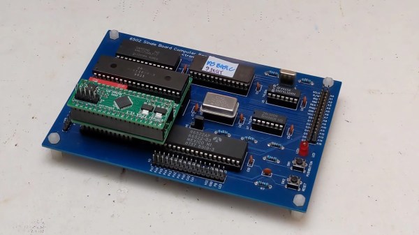
The ROMulator is an FPGA-based board that slots between the 6502 and its socket on whatever computer it came from. It can emulate, but not intercept, accesses to RAM and ROM, which can be used to e.g. replace a ROM that you’re swapping very often or expand the RAM available to the CPU.

In his review, [Jeff] shows the ROMulator in action many computers, notably his custom 6502-based computer, a replica of an Apple 1 and two different replicas of the SUPERBOARD 2. He shows how the ROMulator can be configured, tested, used to debug the computers and even expand their RAM. Overall, [Jeff] thinks it’s a useful 6502 debugger that would have saved him lots of time in the past and we definitely agree.

Continue reading “Debug Your Senile Computers With The ROMulator”

Why The RP1 Is The Most Important Product Raspberry Pi Have Ever Made

We’ve had about a week to digest the pending arrival of the Raspberry Pi 5, and it’s safe to say that the new board from Cambridge has produced quite some excitement with its enhanced specifications and a few new capabilities not seen in its predecessors. When it goes on general sale we expect that it will power a slew of impressive projects in these pages, and we look forward with keen anticipation to its companion Compute Module 5, and we sincerely hope eventually a Raspberry Pi 500 all-in-one. It’s the latest in a line of incrementally-upgraded single board computers from the company, but we think it conceals something of much greater importance than the improvements that marked previous generations. Where do we think the secret sauce lies in the Pi 5? In the RP1 all-in-one PCIe peripheral chip of course, the chip which provides most of the interfacing on the new board. Continue reading “Why The RP1 Is The Most Important Product Raspberry Pi Have Ever Made”

[Ken] Looks At The 386

The 80386 was — arguably — Intel’s first modern CPU. The 8086 was commercially successful, but the paged memory model was stifling. The 80286 also had a protected mode, which differed from the 386’s. [Ken Shirriff] takes the 386 apart for us in a recent blog post.

The 286’s protected mode was less successful than the 386 because of several key limitations as it was a 16-bit processor with a 24-bit address bus. It still required segment changes to access larger amounts of memory, and it had no good way to call back into real mode for compatibility reasons. The 386 fixed all that. You could adopt a segment strategy if you wanted to. But you could also load the segment registers once to point to a 4 GB linear address space and then essentially forget them. You also had a virtual 86 mode that could simulate real mode with some work.

The CPU used a 1-micron process, compared to the 1.5-micron process used earlier. The chip had 285,000 transistors (although the 80386SL had many more). That was ten times the number of devices on the 8086. The cheaper 386SX did use the 1.5 micron process for a while, but with a 16-bit external bus, this was feasible. While 285,000 sounds like a lot, a Core i9 has around 4.2 billion transistors. Times have changed.

A smaller design also allowed chips like the 386SL for laptops. The CPU took up only about a fourth of the die. The rest held bus controllers and cache interfaces to cut costs on laptops. That’s why it had so many more transistors.

[Ken] does his usual in-depth analysis of both the die and the history behind this historic device. We spent a lot of time writing protected mode 386 code, and it was nice to see the details of a very old friend. These days, you can get a pretty capable CPU system on a solderless breadboard, but designing a working 386 system took a few extra parts. The 80286 was a stepping stone between the 8086 and 80386, but even it had some secrets to give up.

A workbench with a 3D printer, a home-made frame of metal tubing and 3D printed brackets and phone holders. 3 iOS devices and 1 Android phone arranged around the printer with a clock and 3 different camera angles around the print bed

Even 3D Printers Are Taking Selfies Now

We love watching 3D prints magically grow, through the power of timelapse videos. These are easier to make than ever, due in no small part to a vibrant community that’s continuously refining tools such as Octolapse. Most people are using some camera they can connect to a Raspberry Pi, namely a USB webcam or CSI camera module. A DSLR would arguably take better pictures, but they can be difficult to control, and their high resolution images are tougher for the Pi to encode.

If you’re anything like us, you’ve got a box or drawer full of devices that can take nearly as high-quality images as a DSLR, some cast-off mobile phones. Oh, that pile of “solutions looking for a problem” may have just found one! [Matt@JemRise] sure has, and in the video after the break, you can see how not one but four mobile phones are put to work.

Continue reading “Even 3D Printers Are Taking Selfies Now”