[Dennis] of [Made by Dennis] has been building a Voron 0 for fun and education, and since this apparently wasn’t enough of a challenge, decided to add a number of scratch-built improvements and modifications along the way. In his latest video on the journey, he rigorously calibrated the printer’s motion system, including translation distances, the perpendicularity of the axes, and the bed’s position. The goal was to get better than 100-micrometer precision over a 100 mm range, and reaching this required detours into computer vision, clock synchronization, and linear algebra.
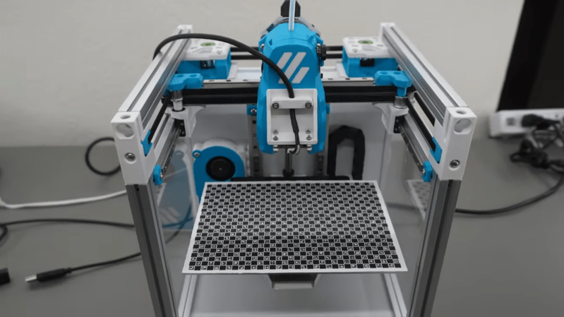
To correct for non-perpendicular or distorted axes, [Dennis] calculated a position correction matrix using a camera mounted to the toolhead and a ChArUco board on the print bed. Image recognition software can easily detect the corners of the ChArUco board tiles and identify their positions, and if the camera’s focal length is known, some simple trigonometry gives the camera’s position. By taking pictures at many different points, [Dennis] could calculate a correction matrix which maps the printhead’s reported position to its actual position.
Leveling the bed also took surprisingly deep technical knowledge; [Dennis] was using a PZ probe to detect when the hotend contacted the bed in various places, and had made a wiper to remove interfering plastic from the nozzle, but wasn’t satisfied by the bed’s slight continued motion after making contact (this might have introduced as much as five micrometers of error). To correct for this, he had the microcontroller in the hotend record the time of contact and send this along with the hit signal to the Raspberry Pi controller, which keeps a record of times and positions, letting the true contact position be looked up. This required the hotend’s and the printer’s microcontrollers to have their clocks synchronized to within one microsecond, which the Pi managed using USB start-of-frame packets.
The final result was already looking quite professional, and should only get better once [Dennis] calibrates the extrusion settings. If you’re looking for more about ChArUco boards, we’ve covered them before, as well as calibration models. If you’re looking for high-precision bed leveling, you could also check out this Z sensor.
Thanks to [marble] for the tip!


Whenever i’ve done this kind of calibration, i’ve been surprised how easy it is to get much better than 1mm precision. Though i felt i had to be a little bit clever to make the best plane out of my most recent bed’s limited adjustments…at first i tried to get everything leveled at the print head’s “0”, and it took a while doing a tug-of-war (pulling it closer here makes it further away somewhere else) before i realized actually the absolute offset doesn’t matter (since the printer calibrates that out perfectly), so instead i tried to find the natural plane it wanted to be on and then got everything as close to that plane as i could. Calculated the triangle error across my 300mm square build plate from the slope and it’s tiny. It’s not better than 0.1mm but it’s pretty close.
But i don’t think there’s any point to doing any better than about +/0.1mm, and i think this write up kind of demonstrates why….you can’t compensate for the bed warping 0.005mm by using more precise measuring, because the bed will warp this much during regular usage too. You can’t meaningfully apply a static calibration for something that will be varying in practice. As someone just pointed out to me in the other article, simply adding weight to the bed will change its shape and height a little bit. The overall characteristics of the process simply don’t support that kind of precision.
When I did measurements on heated bed shapes at Ultimaker, it took 30 minutes before it would settle into it’s final shape after heating up. With deviations as much as 0.1mm during that half hour.
a common pre-print preparation technique these days is to preheat the bed for at least 10minutes ( this low because people are impatient but that’s another story :-D), at 10minutes it’s usually good enough but I do like to soak for 30mins sometimes. From reading your post and the article, the common theme really seems to be ‘your bed probably isn’t the shape you think it is’ and ‘when is good enough, good enough?’. I used to be happy with a saved mesh but these days, especially with 300×300 or 350×350 build plates, there seem to be too many variables that can make the bed a slightly different shape to the one you expected it to be.
I recently upgraded my Prusa Mk4 to Core One and it now has a whole stage before it starts printing where it is “absorbing heat” before running the calibration sequence, I assume this is why.
Also it’s quite incredible that this is the level of precision printers have reached now.
9:10-9:33: If the calibration pattern has been printed with skew, rotating it by 180° and averaging the result of both measurements will not cancel out the skew. You’d need to print it on a transparent sheet and make the second measurement with it flipped on its back to cancel out the skew.
TIL
Unless I’m missing something this feels like solving a problem that machinists solved 100 years ago but in a more complicated way.
100 micrometer is 0.1mm which in machining terms is a barn door, I thought even a cheap printer should be doing better than that these days?
Desktop fdm varies between 0.2-0.5mm. industrial fdm does 0.2mm consistently with some well tuned systems managing 0.1mm.
My fadal 3016 does 0.005 mm.
Thats the difference between open loop stepper motors running belts and closed loop servo motors with digital encoders running precision ball screws. .
I suspect the process of guiding melted plastic has more to do with the limits if precision than individual components. I have little doubt that there are people out there building FDM machines with precision components that don’t see significant gains past the 100microns mentioned here.
Im not debating material limits of poorly regulated thermoplastic flows, just the accuracy of position and repeatability allowed by the mechatronics involved.
Stepper motors, even with microstepping, are never going to come close to the capabilities of a servo motor being tracked with a submicron grade optical linear scale no matter what they are connected to.
Those machinist’s machines are many many thousands of eurs in materials cost alone on dirtiest amateur level and tens to hundreds of thousands of eurs on professional level. They require careful setup and the are basically immovable. They are also immovable because of their weight. Machinist would probably laugh at premium nonDIY printer like Bambu (“precisely” made in factory) that it is a floppy joke.
I move my printer, I tinker with my printer extensively. Each change in gantry requires extremely laborous calibration using Califlower otherwise any errors show hugely when printing ~300mm long things.
Even Bambulab figured it out that one wants to automate this and is using charuco boards and camera. Any bearing or belt change would be hell without it. Yes I consider messing with calibration printsc and calipers and excel an utter hell.
not immovable, just not easily moved.
Three years ago we paid $4k to have a Fadal 4020 (12140 pounds) shipped 1100 miles including loading and offloading. Setup was just levelling, wiring it into the panel and network, and a bunch of tool loading and probing.
Some machines are subject to ITAR and have GPS built in. If you move the machine at all it requires contacting the company to have a tech come out to enter a code.
I heard a story about an earthquake triggering this in a factory and shutting down the facility until someone could enter codes.
Other than that…yeah it is kinda expensive but typically not horrible considering…and at least in my area there are companies that specialize in this.
“I heard a story…”
Im beyond skeptical that any CNC has ever been rigged with a GPS kill switch so sensitive that an earthquake triggered it. Im pretty skeptical that any CNC has ever been required to have such a system implemented. Lets see some reference rather than anecdote.
Should have been more clear I knew it when I hit submit.
It isn’t just GPS. They also have tilt sensors.
The GPS is because people were getting past the tilt sensor stuff.
The machine that was being installed that had the GPS I saw was a Mori mill turn with live tooling. I was told anything past 4 axis had restrictions.
I run a DMG Mori CMX 1100V 4 axis mill with a 2022 manufacturing date stamp at work (along with others), and have read through some of the paperwork for it. If it gets moved you have to call DMG Mori to unlock it, not sure if that includes moving around the building, but does include moving to a different building in the same city. We are actually getting a brand new one of the same model installed atm.
This is basically the same thing as the Bambu Vision Encoder plate for their printers. You pop it on and run the sequence and it uses the camera to accurately check and adjust the toolhead position.
https://us.store.bambulab.com/products/vision-encoder?srsltid=AfmBOoqthvSsGYXWUtJa-Riz6LUfWitfERzD88NWD72yghET9SogS5NF