Sometimes, as hackers and makers, we can end up with messy lashed-together gear that is neither reliable nor tidy. Rackmounting your stuff can be a great way to improve the robustness and liveability of your setup. If you find this appealing, you might like CageMaker by [WebMaka].
This parametric OpenSCAD script can generate mounts for all kinds of stuff. Maybe you have a little network switch that’s just a tangle of wires on your desk, or a few pieces of audio gear that are loosely stacked on top of each other and looking rather unkempt. It would be trivial with this tool to create some 3D printed adapters to get all that stuff laced up nice and neat in a rack instead.
If you’re eager to get tinkering, you can try out the browser-based version quite easily. We’ve featured similar work before, too—many a maker has trod the path of rackmounting, as it turns out.


That’s some fugly “squired plastic” aesthetics. A better result could be achieved with two bits of sheet steel, tin snips, drill, file and maybe can of spray paint.
I spent plenty of time with the tin snips, Dremel and nibbler tool back in the day. Looks are in the eye of the beholder I guess but it was rare to see something made to look as good as a 3d printed part that way!
And the time! Time has value too. Even if it takes a while to print you can do other things during that time.
There is something to be said for metal brackets all bonded to ground. But this is a solution for devices that weren’t meant to be rack mounted in the first place. No one would think twice about it not being mounted to a grounded plate if it was just sitting on a desk. And if one really wants to they could run some grounding strap in back anyway.
Nothing like a bit of constructive criticism
Mmm. First, if you can’t say anything constructive, stay the fark off HAD.
Second, metalwork is its own art and not for everyone. Any given discipline has its pros and cons. Yes, there is the tendency, particularly with 3D printing, to say everything looks like a nail when all you have is a hammer. But the 3D printer hammer is more capable than many others. In this case, if you don’t like the aesthetics, Bondo and paint would work too. Your particular hammer need not be everyone else’s.
Also, you could just as easily say “Go buy a rack shelf” as there are both generic ones and those custom-made for specific pieces of hardware. This being HAD, however, we should revel not only in doing it ourself, but the many options available to do so.
I for one welcome this idea and want to explore it further as I really could have used this a few weeks ago but was too lazy to sort rack hole spacing and how to split pieces for my print bed.
Given how much of a hassle it was to make the cage splitting feature work, I COMPLETELY understand not wanting to faff about with it. SO MUCH TIME went into making that work, and even more time went into making things not break when splitting a cage as features were added, that I’m pretty sure that was the hardest part of the script to write. Rack hole spacing is a bit weird under EIA-310-D – 1/2-5/8-5/8 is a strange pattern – but trivial by comparison.
We have became an overspecialized civilization.
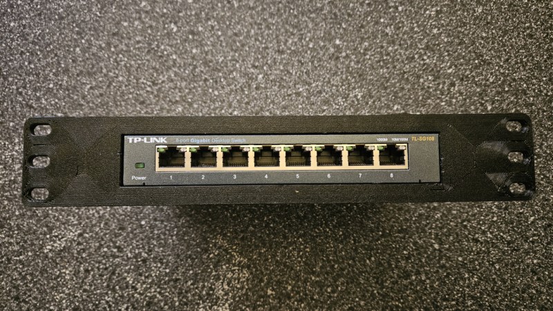
front-mount racks are, IMO, one of those metal-only technologies. because everything’s always got a significant lever arm. i’d be curious to know how this ages even with a light-weight device like the pictured 8-port switch
Agreed. I’d want some sort of connection to the back of the rack for any 3d printed rack mount for that reason, no matter the weight it’s holding.
I have the first cage this script was used to generate holding a MS-01, and thus far it hasn’t moved or started sagging. The script was designed to counter cantilevering through its support geometry, and has options for increasing rigidity for heavier devices such as adjustable thickness and faceplate reinforcing. The latest version can also generate a matching support cage that bolts to rear rails and dovetails into the back of the device cage to form a ladder structure to resist gravity further.
Totally agree. I have 19″ rack equipment (vintage PDP-11) where the CPU and peripherals are between 2RU and 6RU and weigh from just a few kg to over 40kg each. For instance a 3RU paper tape reader is able to support itself by the front rack screws alone because it is high and not that deep, say 1/3 depth. Yet a 2RU magnetic tape formatter is 3/4 rack depth, weighs perhaps 5kg and needs an underslung brace (I folded it from from rectangular flat aluminium bar) to support it properly on the front screws only. Plastic is not a replacement in my situation.
Correction the paper tape reader is 4RU not 3RU
If it’s 40Kg yes this ain’t going to do it but if it’s a light weight switch this is good enough.
Doesn’t have to be metal. Just have to use the correct plastics. I’ve got a printed, 4 inch extender holding up a Ubiquiti PDU. It’s been in there for at least a year, and the PDU isn’t particularly light.
People have a habit of grossly underestimating just how strong a 3d print can be.
And the geometry of the print makes a tremendous difference. This script generates a plus-shaped support structure so it can be more rigid without requiring a ton of excess bulk.
Agreed – I have a pair of rack ears I designed and printed for a pfSense appliance (because despite the fact that it has rack ear screw holes, they don’t sell the ears). Its been holding it without dip for almost 5 years…
I have 3d printed rack mounts for my homelab from Rackify on Etsy and they’ve held up just fine long term.
Being an OpenSCAD bigot myself, I tried it out briefly and my observation was that whilst it seems extraordinarily capable, it doesn’t seem to have a notion of Rack Units (1 RU = 1.75″) which is the standard rack height dimension.
Well I didn’t see such a thing under the Rack Geometry customiser or Device Height, only a whatever-you-like metric height value. I searched the code and no ‘rack unit’ or variations thereof. Also it seems pure metric which is ok for me but there are some countries in the world whose residents that may not feel quite as enamoured.
A suggestion I can think of is that there are so many options available that a series of pairs of small screenshots as numbered Figs (and the customiser texts mentioning which Fig) showing the before/after effect of a setting would be useful, much like the OpenSCAD guide itself. The QuckStart Guide doesn’t give a lot of help but pushes you onto an ‘OpenSCAD Playground’ thing which I didn’t bother checking out.
The choices of rack geometry are defined on lines 513 and following; the unit height is specified as 44.45 mm, equal to 1.75″, for EIA-310 and its variants. Obviously the non-standard options (20mm, 25mm, etc.) specify their respective non-standard unit heights instead.
It determines how many units tall to make the cage based on the size of cage needed. So if the device height + cage floor & ceiling adds up to between 1.75″ and 3.5″, for instance, it spits out a 2U cage.
As for demonstrations of each option, the github wiki has a ConfigOptions page that seems close to what you’re looking for.
Line 513 you reckon?
Why i just knew i should have looked there first instead of the customised height drop downs for 1RU, 2RU and so on! Thanks!
It sounds like you may have your OpenSCAD customizer set to only show option names or a reduced/truncated description. Make sure you have both option name and full description turned on in the customizer (Show Details > Show Details again) – every option has a reasonably detailed description to the extent that OpenSCAD allows due to length constraints.
EDIT: Correction: the “Show Details” button may show as “Hide Details” or “inline Details” depending on the current mode.
The EIA-310 modes all assume a standard rack height of 1.75″/44.45mm, and cage height is automatically scaled based on device height plus the support structure that contains the device, which adds 14mm by default. Non-EIA-310 modes will use the height listed. I can add the heights for EIA-310 to the customizer but I suspect that anyone that knows what EIA-310 even is probably already knows this detail.
The rack geometry parameters are listed in the code along with an explanation of how the array is structured starting on line 512.
Also, the ConfigOptions page in the wiki has explanations of every option along with screenshots of what they do.
Nice rack.
Thanks! It’s very supportive.
I like plastic cages as they make for nice impulse deck greebles .
This is sweet. I like the two-piece bolt together design. I was concerned that my printer wasn’t large enough
I love this idea, but I am concerned about how the PLA will handle the heat of the equipment in the racks. I do live sound and sometimes i have to stage my gear in the sun and it gets HOT. Have you done any torture tests on this yet?
The first cage this script was ever used to generate is currently in my rack holding a Minisforum MS-01. It has not sagged that I can tell. It was printed with what-even-is-this-brand US$20-a-kilo PETG.
Also, PLA isn’t the right choice for this application – PETG at a minimum, and ideally an engineering filament with a higher deformation temperature such as ASA or polycarbonate.
This is very cool! Thanks for sharing… I have a bunch of things that I’d like to rack mount but haven’t had the time to customize each one.